
Assembly and system for pumping a volume of fluid through a body of water

a technology of fluid through a body of water and a system, which is applied in the direction of water installations, floating buildings, construction, etc., can solve the problems of supplying the volume of water, death and destruction of property, and achieve the effect of reducing the distance the vessel needs to move over time, increasing the pneumatic force, and increasing the length

Inactive Publication Date: 2019-09-12
S RATNAM SRI SKANDA RAJAH
View PDF6 Cites 0 Cited by
  • Summary
  • Abstract
  • Description
  • Claims
  • Application Information

AI Technical Summary

Benefits of technology

The present invention is about a new invention that allows for efficient pumping of fluids by using large quantities of low pressure gas and a large floating vessel, pipeline system, and control valves. The invention combines the movement of air and gas to create a very energy efficient movement of fluids. During the process of filling and emptying the vessel, a system of valves separates the inflows and outflows into separate pipes, with the inflow pipe coming in from the source of the water and the outflow pipe connected to a receiving or transporting source that might be a rigid, semi-rigid or flexible vessel used to transport the water to its final destination. The invention also allows for the use of large diameter pipes to increase in length and reduce the distance the vessels need to move over time. Another aspect of the invention is to have one or more pumping systems to feed or remove water from large reservoir bladders submerged in the seas and oceans. The invention can be used to collect and move non-hazardous fluids, slurries, hazardous spills, leaks, and other fluids in an efficient manner.

Problems solved by technology

The world is facing serious challenges in the management of water due to climate change, which has caused rainfall patterns to become unpredictable and creating serious ramifications for food production and survival of communities living in these areas prior to changed rainfall patterns.
Further, arid areas of the world are expanding and one of the more serious consequences is conflict over water resources especially in rivers shared by two or more countries.
Whilst in theory this is good, supplying the volume of water to support this increased area for the growth of plants remains a major challenge as rivers in areas around the arid regions of the world are also experiencing lower and unpredictable flows due to climate change and supporting activities of increased populations in their respective areas.
Whilst some areas of the world face water shortage, there are also many other areas in the world that have too much rainfall.
This excess water problem often results in death and destruction of property due to flooding.
Existing bulk handling of water across water bodies has been limited to large ships or bulk carriers.
These bulk carriers with thick steel hulls and holding areas are expensive and take very long periods of time to build.
The use of these carriers which currently are used to transport primarily oil, gas and other more expensive chemicals would be too prohibitive for the transport of agricultural grade water.
In recent times the use of large floating zippered flexible bags containing as much as 3,000 cubic metres of water has also been attempted but the acceptance has been slow due to damage and tearing of the bags during towing operations that can extend to hundreds or even thousands of kilometres.
The main reason for the failure of this has been that transport of the bags has been limited to the shallow water depths below the surface of the water body which area is both turbulent during storms as well as the area in which a lot of floating debris are present and can damage and tear the membrane of the bags.

Method used


Image

  • Assembly and system for pumping a volume of fluid through a body of water
  • Assembly and system for pumping a volume of fluid through a body of water
  • Assembly and system for pumping a volume of fluid through a body of water

Examples


Embodiment Construction

[0025]Detailed description of preferred embodiments of the present invention is disclosed herein. It should be understood, however, that the embodiments are merely exemplary of the present invention, which may be embodied in various forms. Therefore, the details disclosed herein are not to be interpreted as limiting, but merely as the basis for the claim and for teaching one skilled in the art of the invention. The numerical data or ranges used in the specification are not to be construed as limiting.

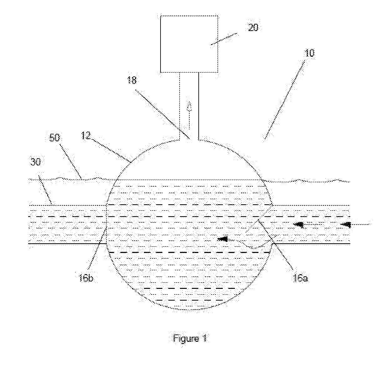
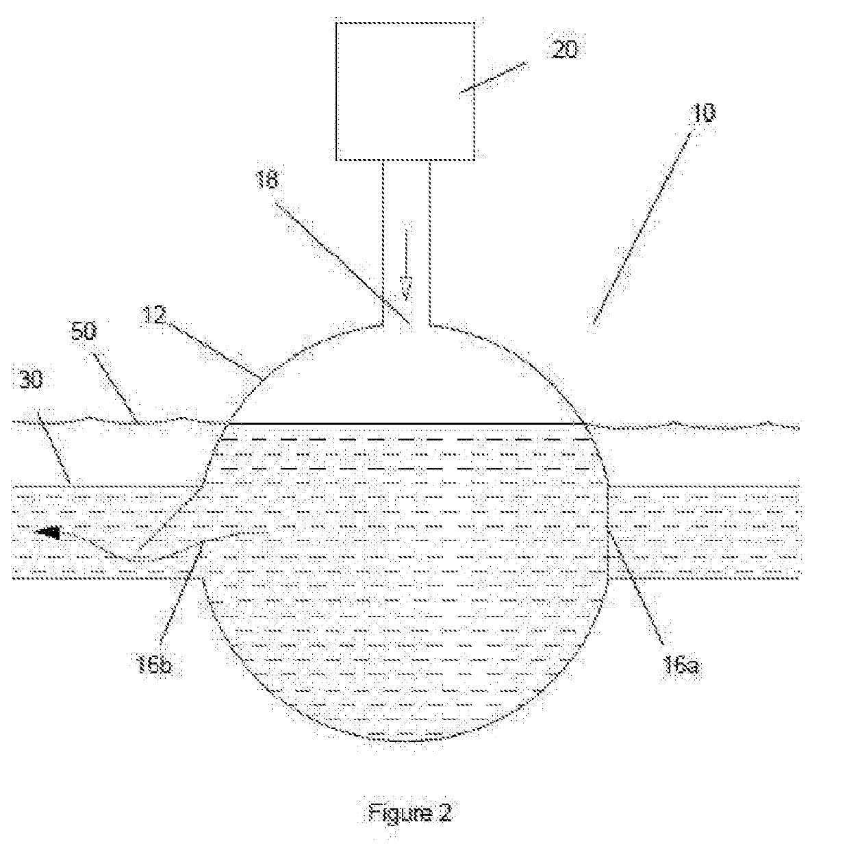
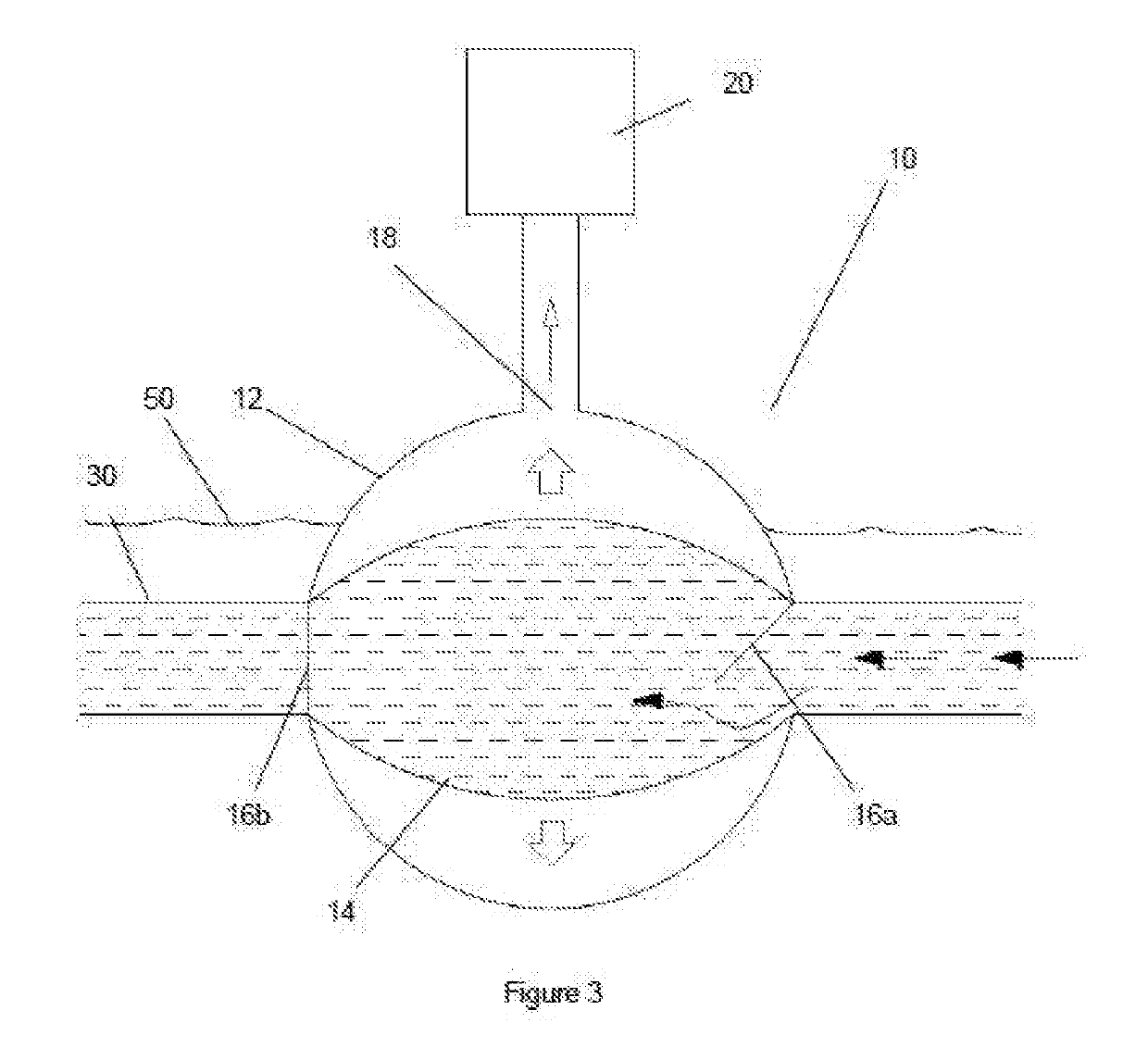
[0026]FIGS. 1 and 2 show a diagrammatic cross-sectional view of a vessel (10) which is an exemplary form of a preferred embodiment of the present invention. The vessel (10) is floating in a body of water and connectable to undersea pipelines (30) that are adapted to be placed in a body of water. While the present invention is chiefly concerned with pumping water from a first location to a second location, it is envisioned that the invention is capable of pumping other types of fluids wh...


PUM


Abstract

An assembly and system for pumping a volume of fluid over a body of water, comprising a shell (12) defining a volumetric space within a vessel (10) in which air is extractible from and introducible into, an opening (18) to allow air to be extracted from and supplied into the vessel (10) to allow fluid to be drawn in and expelled from the vessel (10), a first valve (16a) and a second valve (16b) to permit and restrict fluid entering and exiting the vessel (10) and a pump (20) to extract and introduce air from and into the vessel (10) to cause fluid to be drawn into and expelled out of the vessel (10). The vessel (10) floats in the body of water.

Description

FIELD OF INVENTION[0001]The present invention relates to an assembly and system for pumping a volume of fluid through a body of water. More particularly, the present invention relates to an assembly and system for pumping a large volume of fluid such as water over a large body of water such as rivers, lakes, and oceans.BACKGROUND OF THE INVENTION[0002]The world is facing serious challenges in the management of water due to climate change, which has caused rainfall patterns to become unpredictable and creating serious ramifications for food production and survival of communities living in these areas prior to changed rainfall patterns. Further, arid areas of the world are expanding and one of the more serious consequences is conflict over water resources especially in rivers shared by two or more countries.[0003]The expanding area of desert caused by the warming of the planet is reducing the areas of the earth covered by plant life. Compounded by the activities of man that also destr...

Claims


Application Information

Patent Timeline
Patent Type & Authority Applications(United States)
IPC IPC(8): F04B43/06F04B43/10E03B5/00B63B35/44
CPCF04B43/10E03B5/00B63B35/44F04B43/06F04F1/02F04F1/06F04F1/10F04F1/12
Inventor S.RATNAM, SRI SKANDA RAJAH
Owner S RATNAM SRI SKANDA RAJAH
Learn More