Heat transfer device

a heat transfer device and heat flow rate technology, applied in the direction of lighting and heating apparatus, instruments, etc., can solve the problems of limited heat flow rate and economic inacceptability of housing high-temperature conductive materials, and achieve good thermal conductance, improve thermal conduction, and improve the adhesion of the layer

Active Publication Date: 2019-09-19
APTIV TECH LTD
View PDF0 Cites 0 Cited by
  • Summary
  • Abstract
  • Description
  • Claims
  • Application Information

AI Technical Summary

Benefits of technology

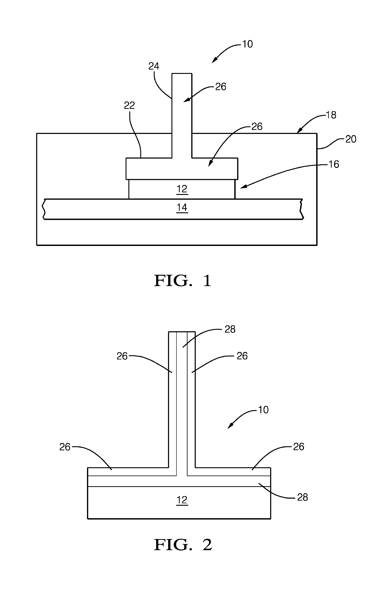
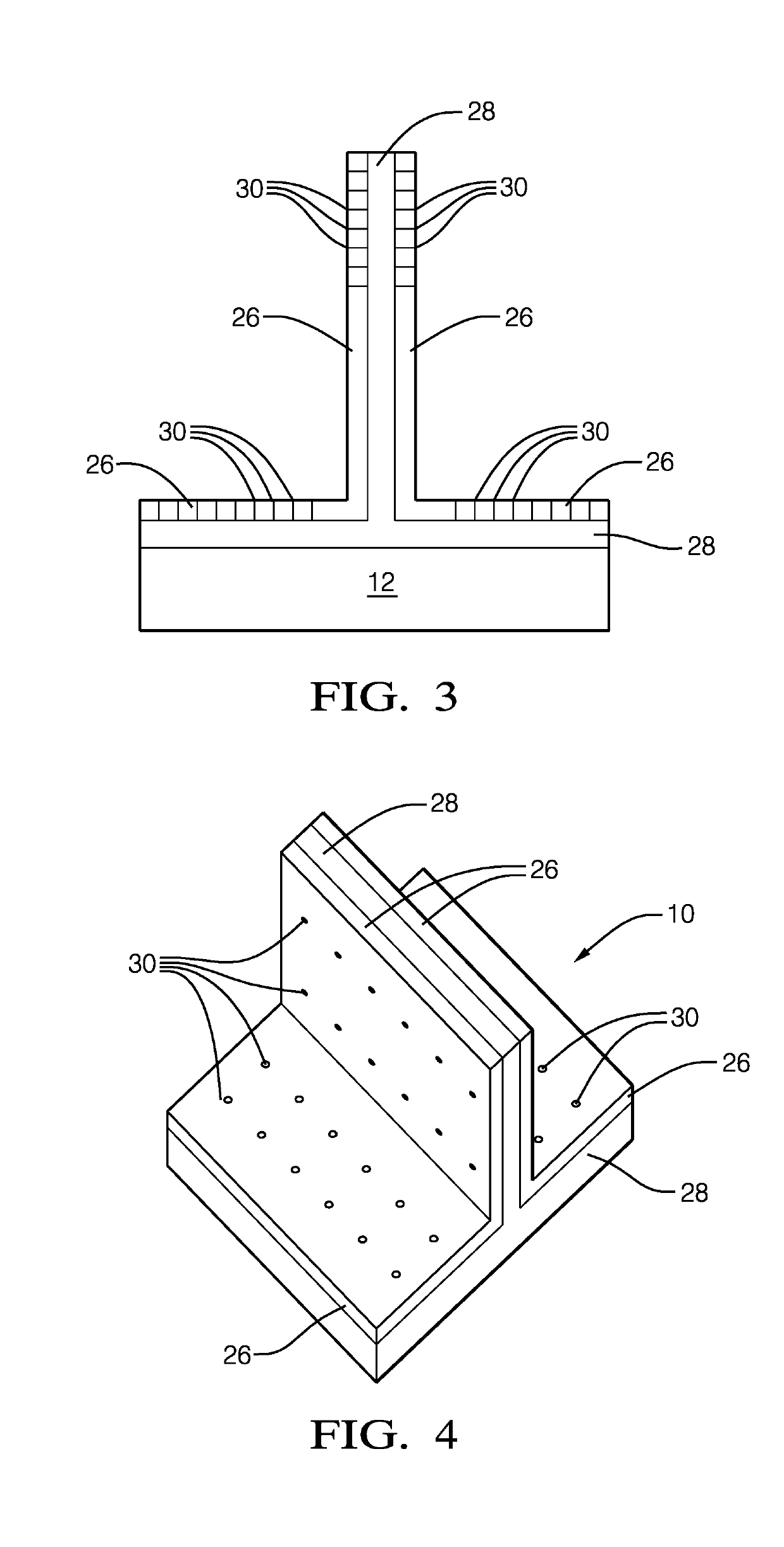
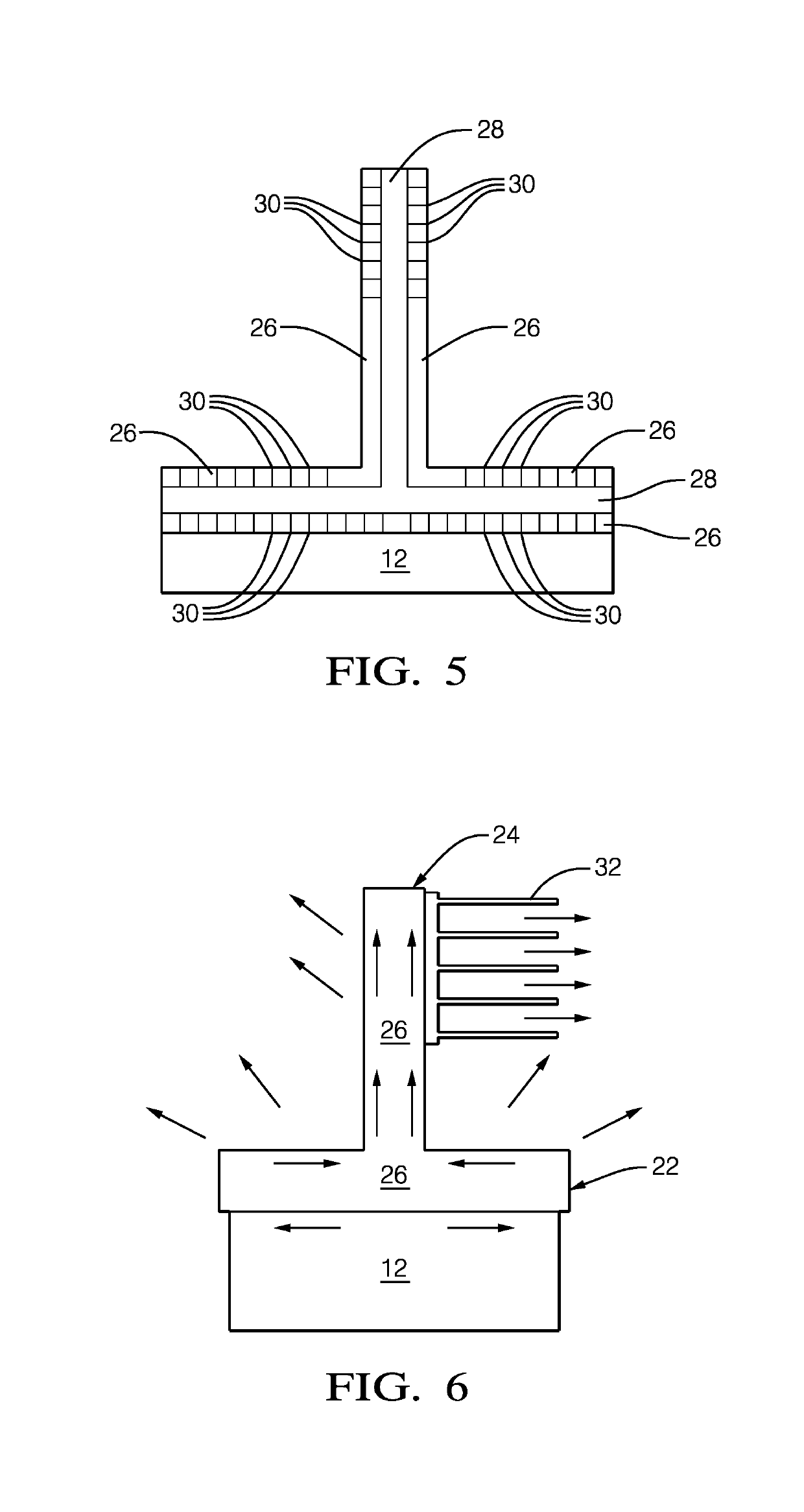
[0020]Advantageously a length of the projections corresponds to at least 50% of a layer thickness of the layer of graphite, in particular to at least 70% of a layer thickness of the layer of graphite, preferably to at least 85% of the layer of graphite and especially of at least substantially 100% of the layer of graphite. Projections of such size ensure a good thermal conductance into the layer of graphite and also an improved adhesion of the layer of graphite to the thermally conducting support layer.
[0021]In this connection it should be noted that it is preferable if a ratio of height to length of the projections is selected in the range of 1:5 to 100:1, especially in the range of 1:2 to 10:1. Such ratios improve the thermal conduction between the heat source and the layer of graphite.

Problems solved by technology

However, the heat flow rate is limited by the heat conductivity of a material of the housing.
Utilization of high thermally conductive materials for the housing can also be economically unacceptable.

Method used


Image

  • Heat transfer device
  • Heat transfer device
  • Heat transfer device

Examples


Embodiment Construction

[0039]Reference will now be made in detail to embodiments, examples of which are illustrated in the accompanying drawings. In the following detailed description, numerous specific details are set forth in order to provide a thorough understanding of the various described embodiments. However, it will be apparent to one of ordinary skill in the art that the various described embodiments may be practiced without these specific details. In other instances, well-known methods, procedures, components, circuits, and networks have not been described in detail so as not to unnecessarily obscure aspects of the embodiments.

[0040]‘One or more’ includes a function being performed by one element, a function being performed by more than one element, e.g., in a distributed fashion, several functions being performed by one element, several functions being performed by several elements, or any combination of the above.

[0041]It will also be understood that, although the terms first, second, etc. are,...


PUM


Abstract

The present invention relates to a heat transfer device, the heat transfer device includes a first plate like structure, and a second plate like structure, with the second plate like structure projecting from the first plate like structure, wherein both the second plate like structure and the first plate like structure each comprise one or more layers of graphite.

Description

TECHNICAL FIELD OF INVENTION[0001]This disclosure generally relates to a heat transfer device.BACKGROUND OF INVENTION[0002]Contemporarily, the computer body electronics thermal management is performed by passive (if existing heat fluxes are of lower values) or active methods (for higher heat fluxes). The advantage of the former over the latter is, that the passive systems do not need an external power source to operate and, due to absence of movable components, are less prone to malfunction. For this reason, this class of thermal management systems is preferable in the automotive design.[0003]Heat transfer in any cooling system is based on three physical phenomena, namely: conduction, convection and radiation. In a standard body electronics passive cooling system, heat is transferred from a source and dissipated to the ambient through a thermal path consisting of thermal interface material, by e.g. a housing and, if possible, a radiating surface, in order to increase heat dissipatio...

Claims


Application Information

Patent Timeline
Patent Type & Authority Applications(United States)
IPC IPC(8): F28F21/02H01L23/367H01L23/373
CPCF28F21/02H01L23/3675H01L23/3735G06F1/20H01L23/373H01L23/3736
Inventor FRUEND, MARCELKORTA, JAKUB
Owner APTIV TECH LTD
Why Eureka
Try Eureka