

Liquid crystal display device and drive method for same
a liquid crystal display and drive method technology, applied in the direction of identification means, instruments, optics, etc., can solve the problems of rapid deterioration of the liquid crystal display device, and achieve the effect of preventing color shift and reducing power consumption
- Summary
- Abstract
- Description
- Claims
- Application Information
AI Technical Summary
Benefits of technology
Problems solved by technology
Method used
Image

Examples
first embodiment
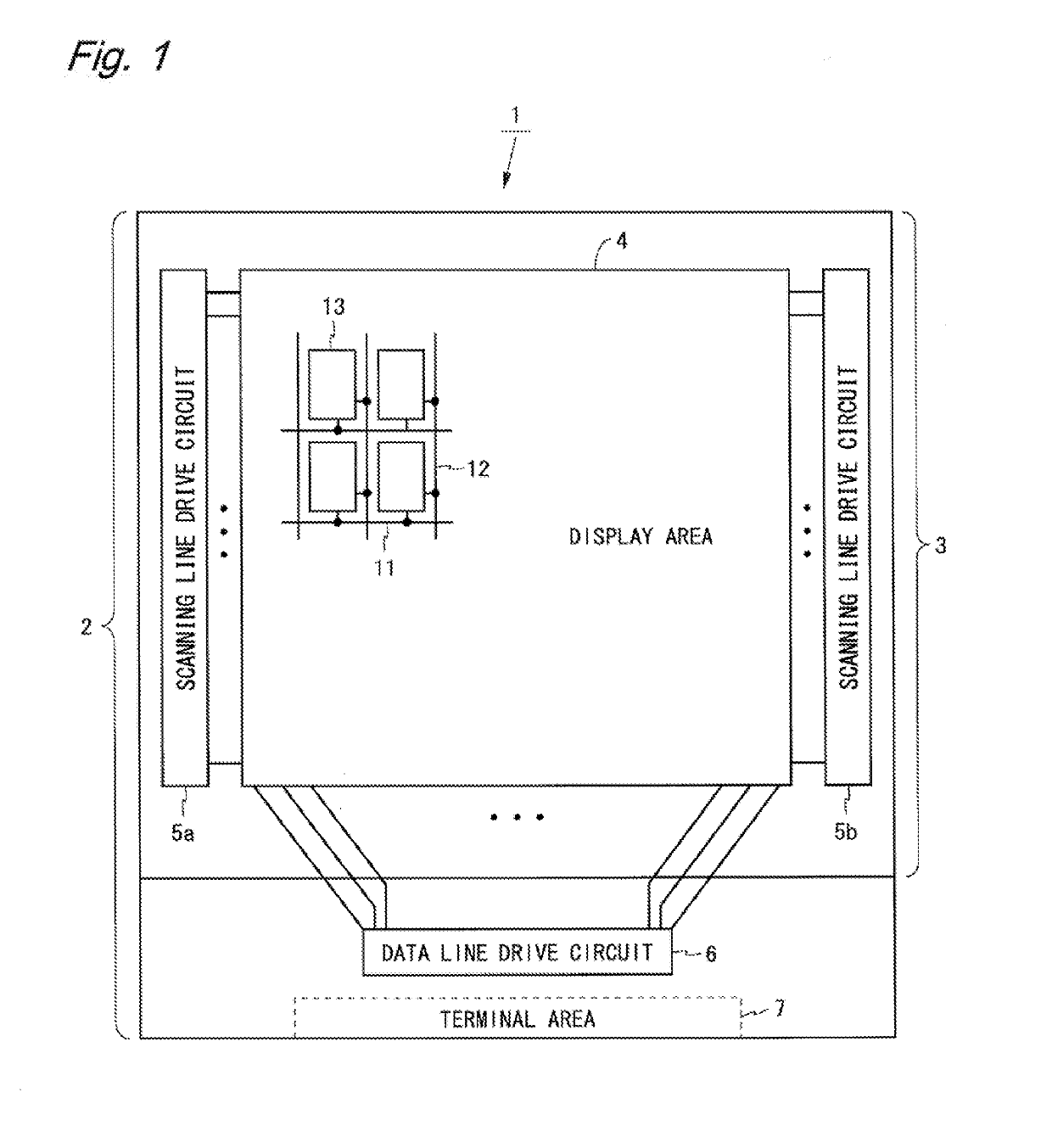
[0033]FIG. 1 is a block diagram showing a configuration of a liquid crystal display device according to a first embodiment. A liquid crystal device 1 shown in FIG. 1 is an active display matrix type display device having a structure in which a TFT substrate 2 and a color filter substrate 3 are bonded to each other and liquid crystal is sealed between the two substrates. The liquid crystal display device 1 displays a color image lasing pixel circuits of three primary colors. The liquid crystal display device 1 includes a backlight not shown in the drawings. Hereinafter, a horizontal direction of the drawings is referred. to as a row direction, a vertical direction of the drawings is referred to as a column direction, a pixel circuit for displaying red is referred to as an a pixel circuit, a pixel for displaying green is referred to as a G pixel circuit, and a pixel circuit for displaying blue is referred to as a B pixel circuit. Furthermore, subpixels corresponding to the pixel circu...
second embodiment
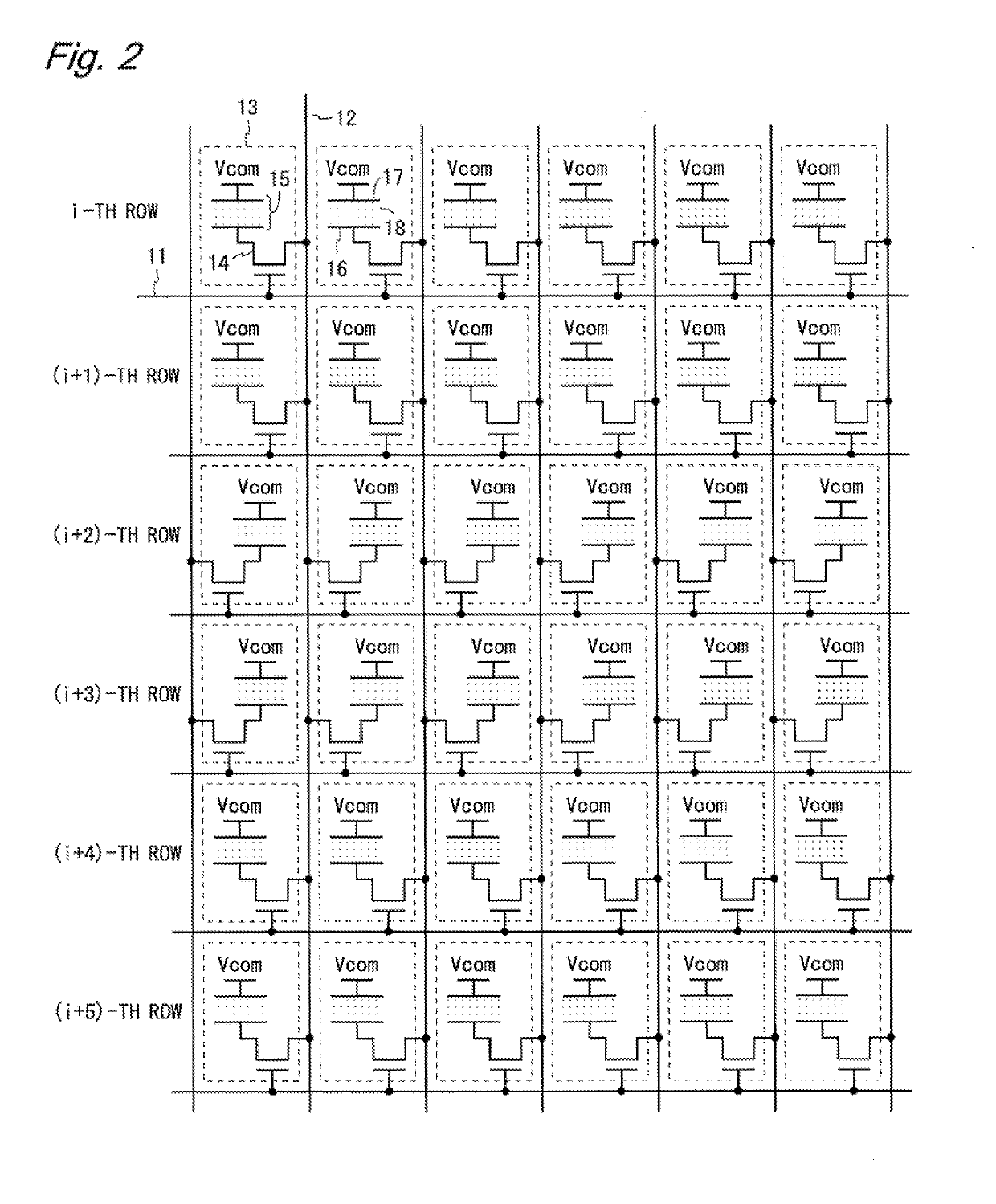
[0067]A liquid crystal display device according to a second embodiment has a same overall structure (FIG. 1) as the liquid crystal display device 1 according to the first embodiment, has a same connection style of the pixel circuits (FIG. 2) as the liquid crystal display device 1, and performs the 2H-Z inversion drive as with the liquid crystal display device 1. Furthermore, the liquid crystal display device according to the present embodiment has a same arrangement of the pixel circuits (FIG. 9) as the liquid crystal display device 1. The liquid crystal display device according to the present embodiment and the liquid crystal display device 1 are different in a layout of the display area 4.
[0068]FIG. 14 is a layout diagram of the display area 4 of the liquid crystal display device according to the present embodiment. As shown in FIG. 14, the scanning line 11 extends in the row direction, and the data line 12 extends in the column direction with bending in a zigzag manner. The pixel...
third embodiment
[0073]A liquid crystal display device according to a third embodiment has the same overall configuration (FIG. 1) as the liquid crystal display device 1 according to the first embodiment. The liquid crystal display device according to the present embodiment has a connection style of the pixel circuits different from that in the liquid crystal display device 1, and performs a 3H-Z inversion drive instead of the 2H-Z inversion drive. Differences from the liquid crystal display device 1 according to the first embodiment are described below.
[0074]FIG. 15 is a circuit diagram of the display area 4 of the liquid crystal display device according to the present embodiment. In the liquid crystal display device according to the present embodiment, the pixel circuits 13 are alternately connected to both sides of the data line 12 in units of three. Specifically, as shown in FIG. 15, the pixel circuits 13 in the i-th to (i+2)-th rows are connected to the left side of the data line 12, and the pi...
PUM
 Abstract
Description
Claims
Application Information