Cryogenic cooling system for an aircraft

a technology of cryogenic cooling and aircraft, which is applied in the direction of refrigeration machines, machines/engines, liquefaction, etc., can solve the problems of less efficient design through losses, limited placement and use of gas turbine engines on or within aircraft, and work loss at thermodynamic exchang

Active Publication Date: 2019-09-26
RTX CORP
View PDF0 Cites 7 Cited by
  • Summary
  • Abstract
  • Description
  • Claims
  • Application Information

AI Technical Summary

Benefits of technology

[0111]In addition to one or more of the features described above or below, or as an alternative, further embodiments may include limiting a speed of the electric fan propulsion motor responsive to confirming whether the working fluid is reaching the propulsion motor windings in the liquid state.
[0112]In addition to one or more of the features described above or below, or as an alternative, further embodiments may include decreasing a flow rate of the working fluid from the full cooling flow to a reduced cooling flow prior to disabling a flow of the working fluid from the cryogenic liquid reservoir through the cryogenic working fluid flow control assembly to the propulsion motor windings.

Problems solved by technology

Work can be lost at thermodynamic exchanges where a cooling air branch occurs without imparting a motive force to turbomachinery within a gas turbine engine.
In some instances, pressures and temperatures within a gas turbine engine are constrained due to material properties, which can result in designs that are less efficient through losses than may otherwise be needed.
Placement and use of gas turbine engines may be limited on or within an aircraft due to constraints on air intake, exhaust, fuel supply, and other factors.
Electric propulsion motors can be effective at driving rotating elements but may be limited in use for providing aircraft thrust due to constraints on power density, electric power demand, heating effects, and weight.

Method used


Image

  • Cryogenic cooling system for an aircraft
  • Cryogenic cooling system for an aircraft
  • Cryogenic cooling system for an aircraft

Examples


Embodiment Construction

[0174]A detailed description of one or more embodiments of the disclosed apparatus and method are presented herein by way of exemplification and not limitation with reference to the Figures.

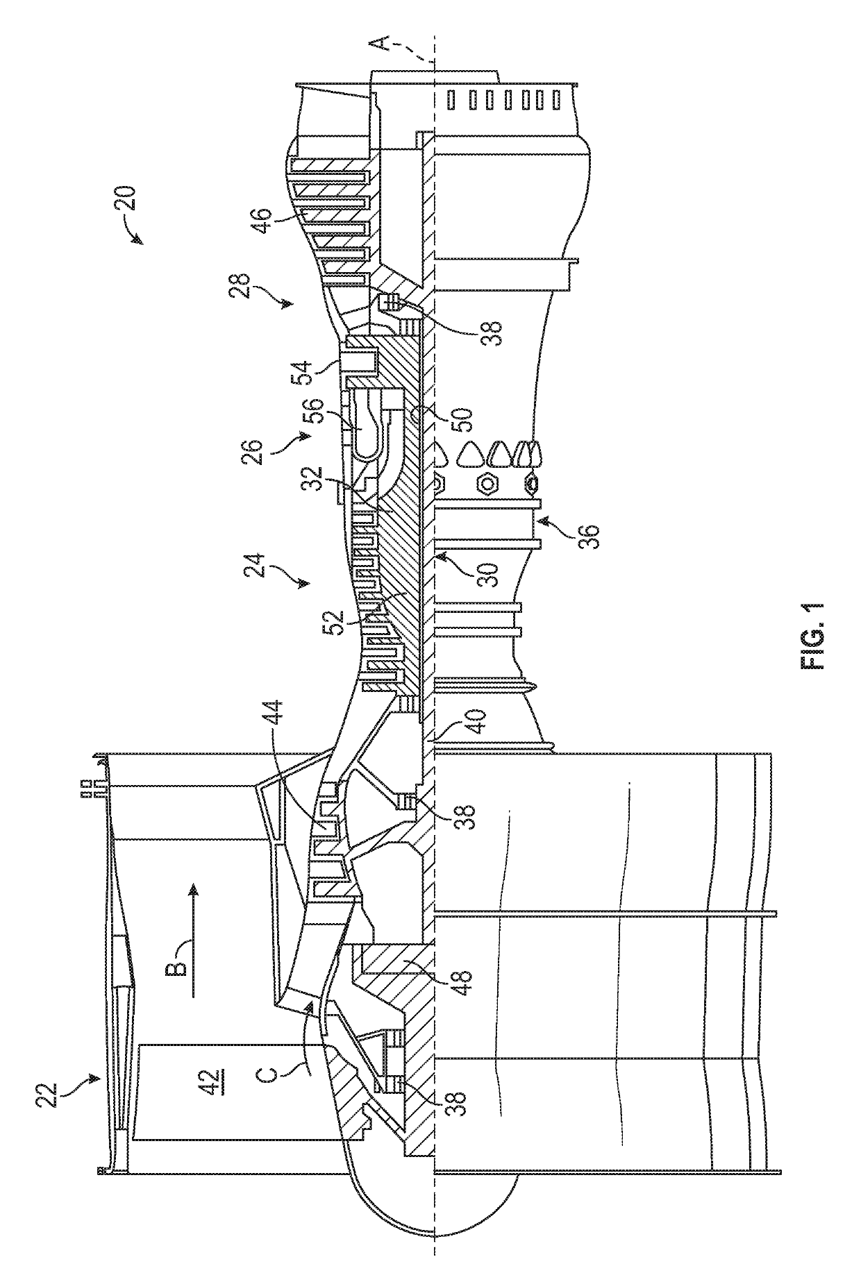
[0175]FIG. 1 schematically illustrates a gas turbine engine 20. The gas turbine engine 20 is disclosed herein as a two-spool turbofan that generally incorporates a fan section 22, a compressor section 24, a combustor section 26 and a turbine section 28. The fan section 22 drives air along a bypass flow path B in a bypass duct, while the compressor section 24 drives air along a core flow path C for compression and communication into the combustor section 26 then expansion through the turbine section 28. Although depicted as a two-spool turbofan gas turbine engine in the disclosed non-limiting embodiment, it should be understood that the concepts described herein are not limited to use with two-spool turbofans as the teachings may be applied to other types of turbine engines including three-spool a...


PUM

PropertyMeasurementUnit
speedaaaaaaaaaa
speedaaaaaaaaaa
pressureaaaaaaaaaa

Abstract

A cryogenic cooling system for an aircraft includes a first air cycle machine, a second air cycle machine, and a means for collecting liquid air. The first air cycle machine is operable to output a cooling air stream based on a first air source. The second air cycle machine is operable to output a chilled air stream at a cryogenic temperature based on a second air source cooled by the cooling air stream of the first air cycle machine. An output of the second air cycle machine is provided to the means for collecting liquid air.

Description

CROSS-REFERENCE TO RELATED APPLICATION[0001]This application claims the benefit of priority to U.S. Provisional Application No. 62 / 647,055 filed Mar. 23, 2018, U.S. Provisional Application No. 62 / 647,060 filed Mar. 23, 2018, U.S. Provisional Application No. 62 / 653,599 filed Apr. 6, 2018, U.S. Provisional Application No. 62 / 653,602 filed Apr. 6, 2018, U.S. Provisional Application No. 62 / 653,604 filed Apr. 6, 2018, U.S. Provisional Application No. 62 / 656,451 filed Apr. 12, 2018, and U.S. Provisional Application No. 62 / 656,453 filed Apr. 12, 2018, the disclosures of which are incorporated herein by reference in their entirety.BACKGROUND[0002]Exemplary embodiments pertain to aircraft systems, and more particularly to systems and methods of cryogenic cooling on an aircraft.[0003]Gas turbine engines can provide propulsion and power on an aircraft. Aircraft can include separate systems that control propulsion, thermal management, and other functions. Aircraft environmental control systems ...

Claims


Application Information

Patent Timeline
Patent Type & Authority Applications(United States)
IPC IPC(8): B64D13/08F02C7/16F02C7/141
CPCB64D2013/0681F02C7/16F02C7/141F05D2260/232B64D2013/0677B64D37/32B64D13/08F05D2260/211B64D2013/0614B64D33/08B64D2013/0674F02C6/08B64D13/06B64D2013/0659F25J3/04533F25J3/04563F25J3/046F25J3/04975F25J3/0429F25J2215/40F25J2205/86F25J3/04636F05D2260/205F25J1/0012F25J1/0221F25J2210/40F25J2230/30F25J2230/08F25J1/0035F25J1/0275Y02T50/50F02C9/18F25B9/14F25J3/04254F25J2240/42F25J2240/80B01D45/08B01D53/002B03C1/288B64D27/12F01D15/00F01D25/12F02C7/143F02C7/185F02K3/06F05D2220/323F05D2260/60F25J2290/70F17C7/02F17C7/04
Inventor SCHWARZ, FREDERICK M.WINTER, MICHAELLENTS, CHARLES E.SNAPE, NATHANEPSTEIN, ALAN H.
Owner RTX CORP
Why Eureka
Try Eureka