Mixing structure

Active Publication Date: 2019-09-26
HINO MOTORS LTD
View PDF1 Cites 0 Cited by
  • Summary
  • Abstract
  • Description
  • Claims
  • Application Information

AI Technical Summary

Benefits of technology

The mixing structure in this patent allows for easy mixing of exhaust gas and additives. It includes a curved portion and a depression in the exhaust flow passage, which helps to create a spiral flow of exhaust gas. This design also allows for the selective reduction catalyst to be incorporated and enhances the admixture of reducing agents into the exhaust gas. Additionally, the design includes an injector that sprays the reducing agent into the exhaust gas, which ensures a long reaction time for the reducing agent and maximizes the catalytic performance of the selective reduction catalyst to achieve efficient exhaust depuration. Overall, this mixing structure improves the performance and effectiveness of selective reduction catalyst in the exhaust system of automobiles.

Problems solved by technology

However, arrangement of the particulate filter and the selective reduction catalyst in a substantially spaced apart relationship will extremely impair the mountability on a vehicle.

Method used


Image

  • Mixing structure
  • Mixing structure
  • Mixing structure

Examples


Embodiment Construction

[0026]An embodiment of the invention will be described in conjunction with the drawings.

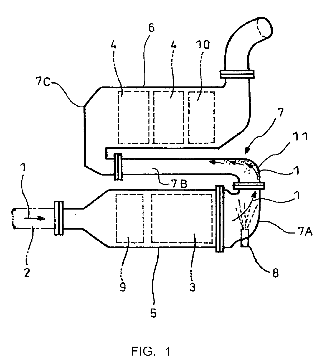
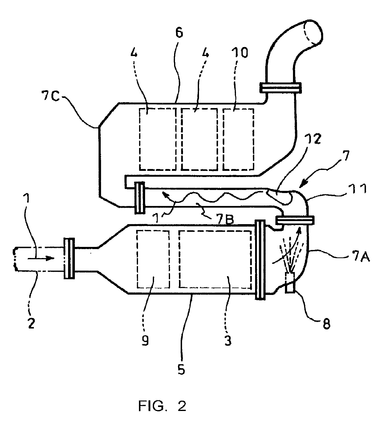
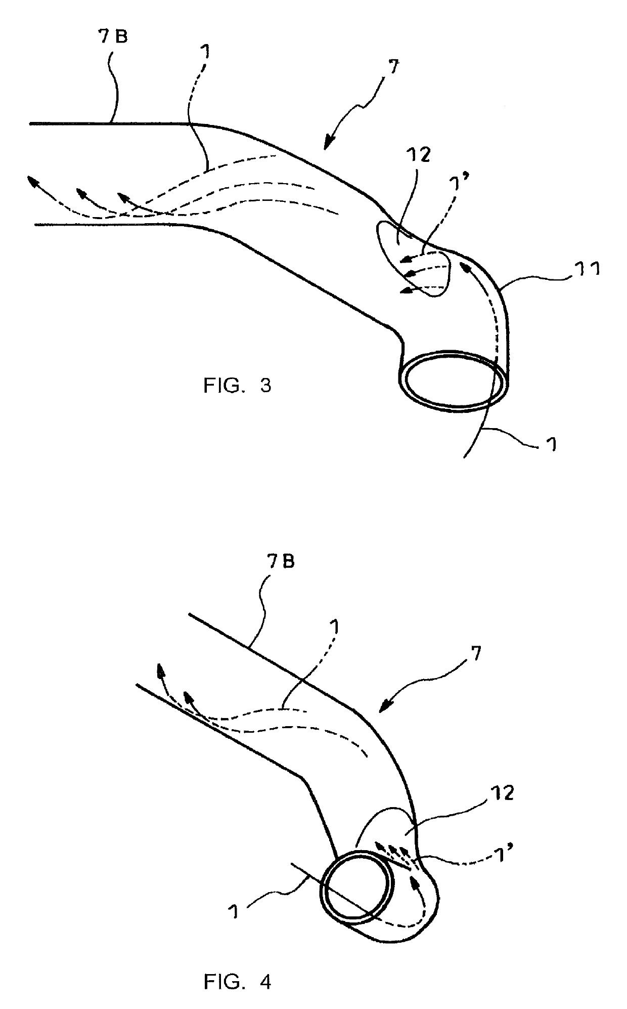
[0027]FIGS. 2-4 show the embodiment of the invention which is constructed substantially similar to the above-mentioned example shown in FIG. 1, is applied to an exhaust emission control device and is characterized in that the mixing structure comprises a curved portion 11 in a communication passage 7 (exhaust flow passage) downstream of a sprayed position of urea water (reducing agent (additive agent)) by an injector 8, and a depression 12 on an exit side of the curved portion 11 and formed on one of sides of the curved portion 11 bisected by a plane into plane symmetry (assumed is plane symmetry in a state that below-mentioned depression 12 is not formed yet). In the illustrated exhaust emission control device in which a particulate filter 3 is arranged in parallel with and is communicated through the S-shaped communication passage 7 with selective reduction catalysts 4, a curved portion 11 alre...


PUM


Abstract

Disclosed is a mixing structure for spraying and mixing urea water (additive agent) into and with exhaust gas 1 flowing through a communication passage 7 (exhaust flow passage). The mixing structure is provided with a curved portion 11 in the communication passage 7 downstream of a sprayed position of the urea water as well as a depression 12 on an exit side of the curved portion 11 and formed on only one of sides of the curved portion 11 bisected by a plane into plane symmetry.

Description

TECHNICAL FIELD[0001]The present invention relates to a mixing structure.BACKGROUND ART[0002]It has been recently proposed that a particulate filter for capturing particulates in exhaust gas is incorporated in an exhaust pipe and a selective reduction catalyst capable of selectively reacting NOx with ammonia even in the presence of oxygen is arranged downstream of the particulate filter, urea water as reducing agent (additive agent) being sprayed at a position between the selective reduction catalyst and the particulate filter, thereby attaining lessening of both the particulates and NOx.[0003]Such addition of the urea water to the selective reduction catalyst is conducted at the position between the particulate filter and the selective reduction catalyst. Thus, in order to ensure sufficient reaction time for pyrolysis of the urea water added to the exhaust gas into ammonia and carbon dioxide gas, it is necessary to prolong a distance between the urea-water added position and the se...

Claims


Application Information

Patent Timeline
IPC IPC(8): F01N3/28B01D53/90B01D53/94F01N3/20F01N13/00
CPCF01N3/28F01N3/208B01D53/9495F01N13/009B01D53/90F01N2610/02B01D53/86B01D53/94F01N3/08F01N3/24Y02T10/12F01N3/2066F01N2610/1453F01N3/2892B01F23/2132F01N2240/20B01D53/9431B01D2251/2067B01F25/3141
Inventor TOMITA, NORIYUKIKAMIYA, TAKAOMINODA, KUMIKO
Owner HINO MOTORS LTD
Why Eureka
Try Eureka