Pinhole contact lens and smart contact system

a technology of contact lens and smart contact system, which is applied in the field of pinhole contact lens, can solve problems such as myopia or hyperopia, and achieve the effects of reducing light diffraction, improving the quality of pinhole image, and high functionality

Inactive Publication Date: 2019-09-26
UNIVERSAL VIEW
View PDF0 Cites 8 Cited by
  • Summary
  • Abstract
  • Description
  • Claims
  • Application Information

AI Technical Summary

Benefits of technology

[0050]According to the pinhole contact lens according to the present invention, it is possible to dynamically correct the brightness around the pinhole image formed on the retina, so an annular gray image (ring image) caused by light diffraction can be reduced.
[0051]Further, according to the present invention, it becomes possible to selectively control a plurality of fine holes pierced on the outer peripheral edge of the light-shielding region. So, the brightness around the pinhole image can be precisely controlled in response to the bright environment and the dark environment. In addition, it is possible to form a real image by the pinhole while, with respect to the real image, synthesizing a virtual image based on control information on the retina.
[0052]As a result, it is possible to make the brain of the contact lens wearer recognize in real time an image or the like based on the control information while maintaining the functions of the conventional fixed hole number type pinhole contact lenses. Therefore, it is possible to provide a smart contact lens which enables quality of a pinhole image to be improved, a correction of all of myopia or hyperopia, astigmatism and presbyopia to cope by utilizing the original depth of focus provided by the pinhole and high functionality to attain.
[0053]The smart contact system according to the present invention includes any of the pinhole contact lenses according to the present invention, thereby making it possible to provide a remote diagnosis treatment comprehensive system using a smart contact lens in which the focal of depth provided by the pinhole is utilized, correction of all of myopia or hyperopia, astigmatism and presbyopia is dealt with, and high functionality such as intraocular pressure, blood sugar and light detection functions are implemented.

Problems solved by technology

At this time, the subject light is focused on a position in front of or behind the retina, resulting in myopia or hyperopia.
In addition, if the cornea or the crystalline lens is distorted, the subject light is not focused on the retina, resulting in astigmatism.

Method used


Image

  • Pinhole contact lens and smart contact system
  • Pinhole contact lens and smart contact system
  • Pinhole contact lens and smart contact system

Examples


first embodiment

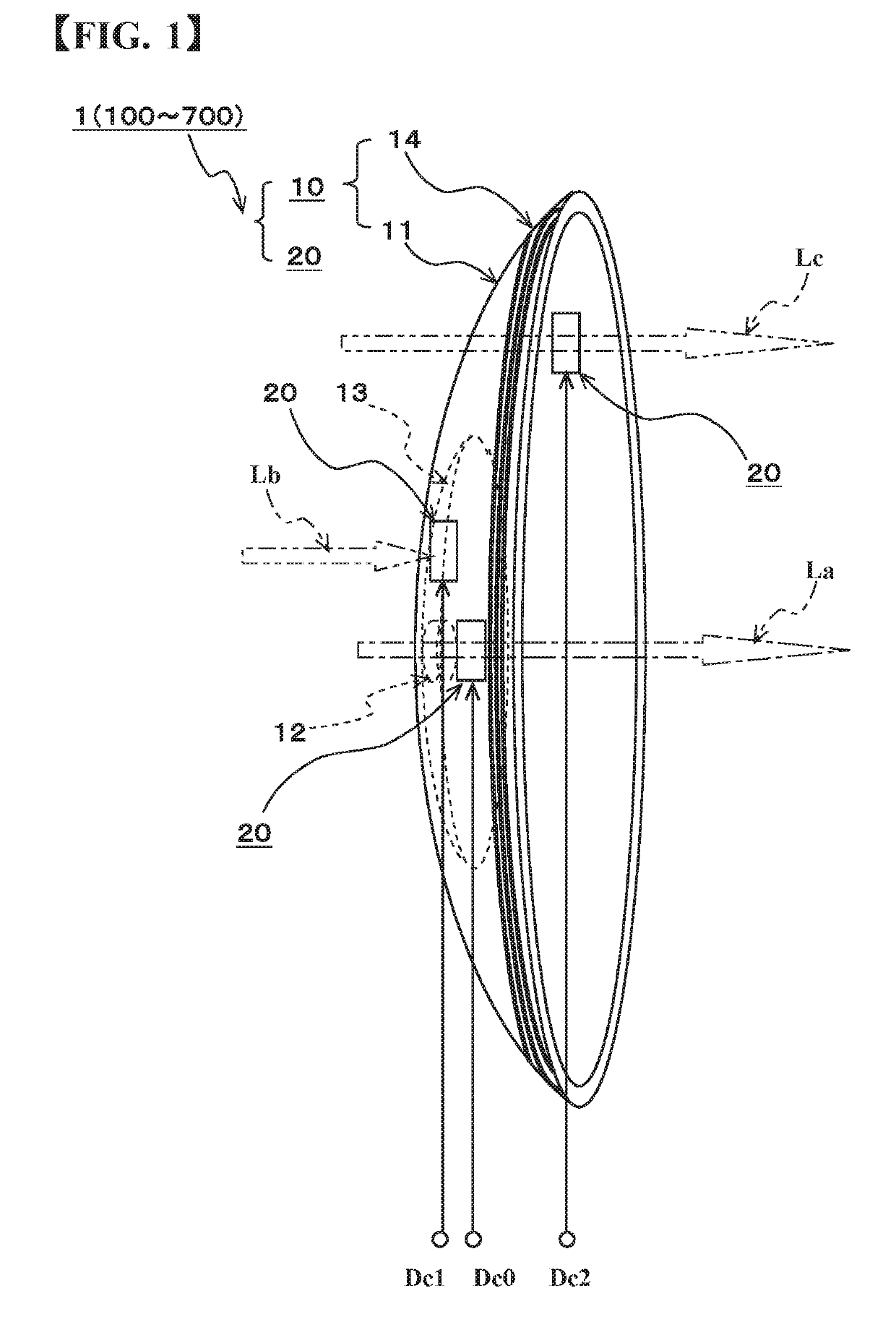
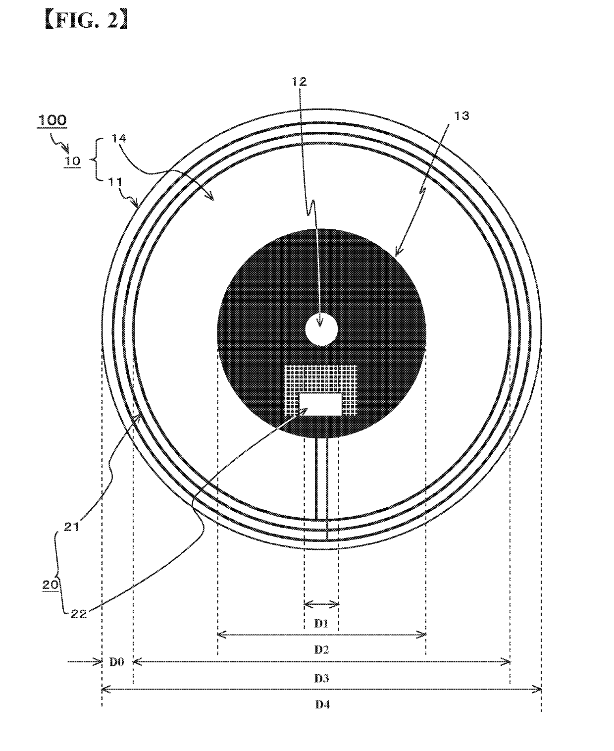
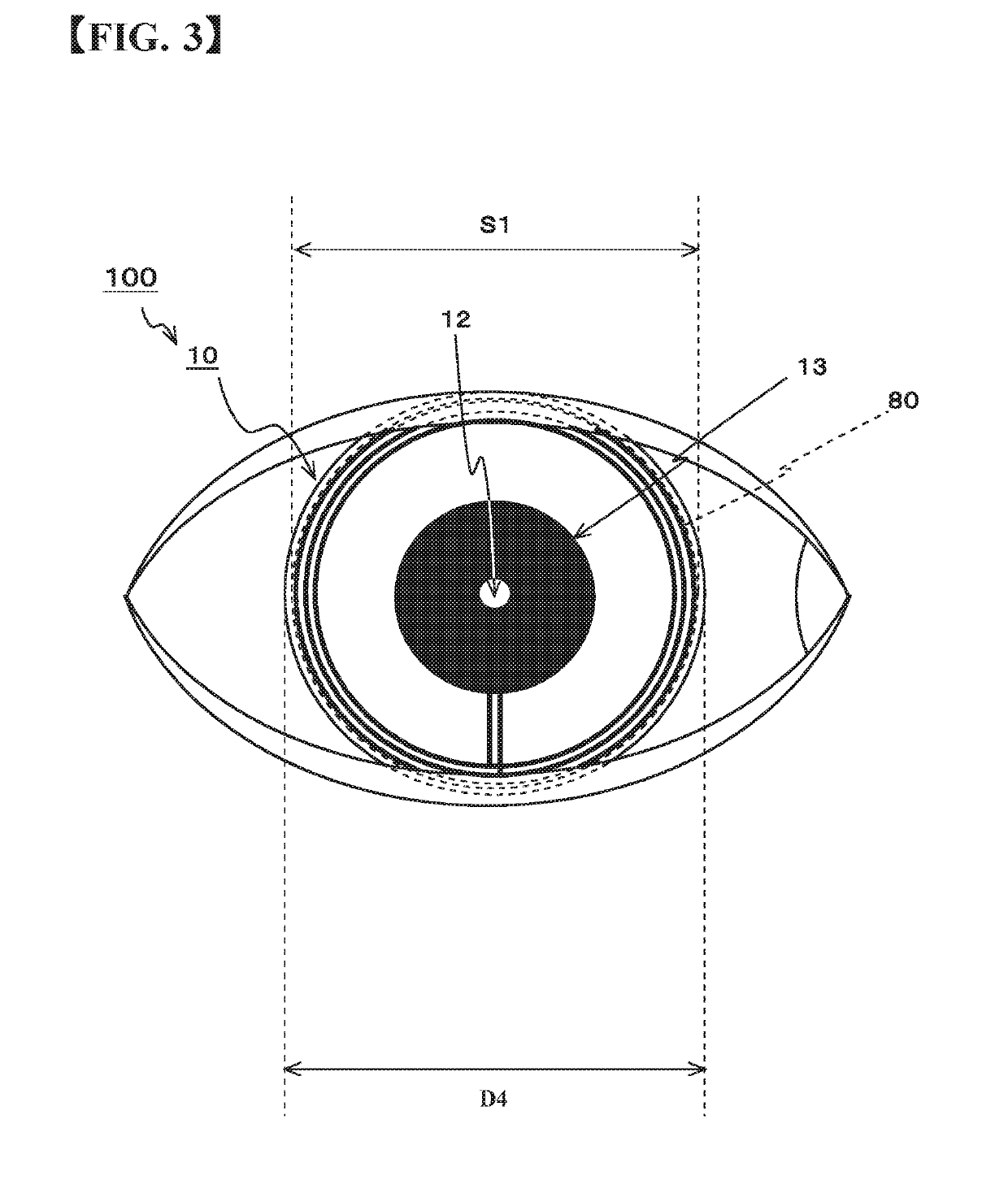
[0076]A pinhole contact lens 1 shown in FIG. 1 is a smart contact lens, and represents a configuration example of any of the pinhole contact lenses 100 to 700 of each embodiment according to the present invention which will be described later. Hereinafter, the configuration example of the pinhole contact lens 1 according to each embodiment will be described using the pinhole contact lens 100 of the first embodiment. In the pinhole contact lenses 200 to 700 of the second to seventh embodiments, the same components as those of the pinhole contact lens 100 of the first embodiment are denoted by the same codes, and the detailed descriptions thereof will be omitted. The pinhole contact lens 100 has a pinhole lens member 10 fittable on the cornea of a person and an electronic member 20 in FIG. 1. The pinhole lens member 10 has a lens member 11. A pinhole region 12 is arranged approximately at the center of the lens member 11, and a beam of light La passing through the pinhole region 12 co...

second embodiment

[0114]In this embodiment, the control unit 25 executes the brightness correction mode. For this reason, the light-shielding region 13 of the pinhole contact lens 200 shown in FIG. 8 is devised. The light-shielding region 13 has the pinhole region 12 and a plurality of (many) holes 15. The liquid crystal display elements 24 are installed to close all or some of the holes 15. Each of the liquid crystal display elements 24 may be arranged either on the upper surface side or on the lower surface side of the light shielding member 13′ as long as the holes 15 can be selected. Although, in FIG. 8, the liquid crystal display elements 24 are arranged in the right half for the sake of convenience in order to explain the distribution of the holes 15, but, of course, are arranged also in the left half. In the relationship between the holes 15 and the liquid crystal display elements 24, a plurality of holes 15 may be selected for one pixel, or one hole 15 may be selected for a plurality of pixel...

third embodiment

[0129]In the third embodiment, the control unit 25 executes the alignment assistance mode. Therefore, the liquid crystal display element 24 is formed in the pinhole region 12 as in the pinhole contact lens 300 shown in FIGS. 10A and 10B. For example, the opening part itself for forming the pinhole image on the retina 86 of the wearer is formed from the liquid crystal display element 24. For the liquid crystal display element 24, for example, PLCD liquid crystal can be used. The PLCD liquid crystal controls transmission of light based on the presence or absence of charge, and, in the case of the reverse type, transmits light in the absence of charge. Of course, the liquid crystal display element 24 is not limited to the PLCD liquid crystal.

[0130]In this embodiment, first, in a step ST11 shown in FIG. 11, the control unit 25 waits for the setting of the alignment assistance mode. When the external device 90 approaches the pinhole contact lens, the wireless communication unit 22 and th...


PUM


Abstract

The invention enables quality of a pinhole image to be improved, any of myopia or hyperopia, astigmatism and presbyopia to be corrected and high functionality to attain. A pinhole contact lens 100 according to this invention includes a pinhole lens member 10 which contains a lens member 11 fittable onto a cornea of a person, a circular pinhole region 12 arranged approximately in a center of the lens member and forming a pinhole image on a retina of a wearer, a light-shielding region 13 provided on an outer peripheral side of the pinhole region 12 and shielding light, and a transparent region 14 provided on an outer peripheral side of the light-shielding region 13 and transmitting the light; and an electronic member 20 which is arranged on any one of the pinhole region 12, the transparent region 14 and the light-shielding region 13 and electrically performs an optical processing on any one of the light transmitted via the transparent region 14 and the light absorbed into the light-shielding region 13 on the basis of any control information, with respect to light passing through the pinhole region, to be applied on the pinhole image.

Description

TECHNICAL FIELD[0001]The present invention relates to a pinhole contact lens using with it being fitted onto a cornea and a smart contact system. Specifically, it relates to a smart contact lens in which an electronic member is arranged in at least any one of a pinhole region, a transparent region and a light-shielding region, and, electrically performs an optical processing on at least any one of the light transmitted via the transparent region and the light absorbed into the light-shielding region on the basis of any control information, with respect to light passing through the pinhole region, to be applied on the pinhole image, and a smart contact system using the same.BACKGROUND ARTS[0002]For an image of a subject visually recognized by a person, light of the subject incident from the cornea is refracted by the cornea and the crystalline lens, enters the vitreous body and is focused on the retina on the rear surface side of the vitreous body, and the imaged visual information i...

Claims


Application Information

Patent Timeline
Patent Type & Authority Applications(United States)
IPC IPC(8): G02C7/04
CPCA61B5/6821A61B3/16G02C7/049G02C7/04A61B3/0008A61B3/14G02C7/16G02C11/10H04B1/385G02B27/0172H04B1/3827G02B1/043G02B5/00
Inventor TAKAKI, YUSUZUKI, TAROSUZUKI, YOSHIONAGAI, KENJIHASHIMOTO, MASARU
Owner UNIVERSAL VIEW
Why Eureka
Try Eureka