HDMI photoelectric composite cable and method for manufacturing the same

a photoelectric composite cable and long-distance technology, applied in the direction of cables, insulated conductors, cables, etc., can solve the problems of large bandwidth and the use length of hdmi cables, and the inability of photoelectric composite cables to perform long-distance transmission, etc., to achieve long-distance transmission, small capacitance, and small signal attenuation

Inactive Publication Date: 2019-09-26
DONGGUAN SINO SYNCS IND
View PDF11 Cites 7 Cited by
  • Summary
  • Abstract
  • Description
  • Claims
  • Application Information

AI Technical Summary

Benefits of technology

[0005]With regard to the above problem, the present disclosure proposes a High Definition Multimedia Interface (HDMI) photoelectric composite cable and a method for manufacturing the HDMI photoelectric composite cable. The HDMI cable has a small capacitance and a small signal attenuation, and thus, can achieve long-distance transmission.

Problems solved by technology

A common HDMI cable takes a metal wire as a transmission carrier, which has disadvantages that a metal wire has a resistance that would accumulatively generate a larger attenuation value with the increase of wire length, causing the signal attenuation.
Therefore, the bandwidth and the use length of HDMI cable are greatly limited.
In an actual use, the capacitance of the photoelectric composite cable is large, causing that the photoelectric composite cable could not perform the long-distance transmission.

Method used


Image

  • HDMI photoelectric composite cable and method for manufacturing the same
  • HDMI photoelectric composite cable and method for manufacturing the same

Examples


Embodiment Construction

[0036]The present disclosure is further described in detail in combination with drawings and embodiments. It should be understood that, specific embodiments described herein are only used for interpreting the present disclosure, rather than limiting the present disclosure. In addition, it should also be noted that, for ease of description, the drawings only illustrate part of structures related to the present disclosure, rather than all structures.

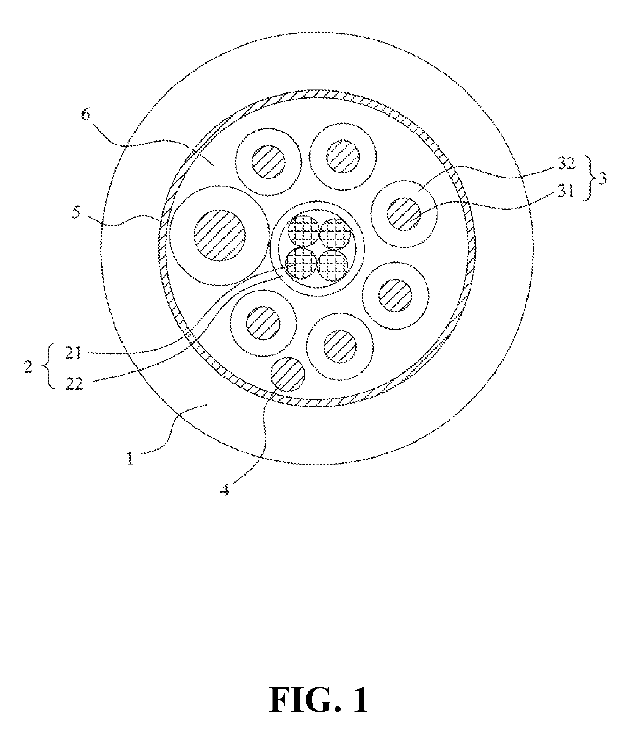
[0037]FIG. 1 is a structural schematic diagram illustrating an HDMI photoelectric composite cable provided by the present disclosure. The HDMI photoelectric composite cable mainly includes a sheath 1, an optical fiber unit 2, signal control wires 3, a ground wire 4 and a shielding layer 5. The sheath 1 is a protective sheath of the whole cable. The ground wire 4 and the shielding layer 5 are configured to shield an external signal from interfering with an internal signal and may also be configured to shield the internal signal of the cable...


PUM

PropertyMeasurementUnit
transmission distanceaaaaaaaaaa
diameteraaaaaaaaaa
transmission distanceaaaaaaaaaa

Abstract

The present disclosure discloses an HDMI photoelectric composite cable. The HDMI photoelectric composite cable includes: a sheath, an optical fiber unit, a plurality of signal control wires, a ground wire and fillers. The optical fiber unit includes one or more optical fibers and an optical fiber sheath uniformly extruded on a periphery of the optical fibers. The signal control wire includes a metal wire and an insulating layer uniformly extruded on a periphery of the metal wire. The ground wire is a metal conductor. The fillers are arranged on peripheries of the optical fiber unit, the plurality of signal control wires and the ground wire. The optical fiber unit, the plurality of signal control wires, the ground wire, and the fillers arranged on the peripheries thereof are covered by the shielding layer, and the shielding layer is covered by the sheath.

Description

CROSS-REFERENCE TO RELATED APPLICATION[0001]This application claims priority to Chinese Patent Application Serial No. CN 201810246260.5, filed on Mar. 23, 2018, the disclosure of which is hereby incorporated herein in its entirety by this reference.TECHNICAL FIELD[0002]The present disclosure relates to the technical field of HDMI long-distance high-definition wires, and particularly to an HDMI photoelectric composite cable and a method for manufacturing the HDMI photoelectric composite cable.BACKGROUND[0003]With increasing development of science and technology, popularization of a 4K TV, and rapid improvement of quality of human life, the requirement for a high transmission rate of a high-frequency wire is increasing. Large screens at large video venues, high-end hotels, supermarkets and outdoor plazas need long-distance HDMI wires. The short HDMI wires may be 30 m to 50 m, and the long ones may be hundreds of meters. A common HDMI cable takes a metal wire as a transmission carrier,...

Claims


Application Information

Patent Timeline
Patent Type & Authority Applications(United States)
IPC IPC(8): H01B11/22G02B6/44H01B7/18H01B7/295H01B3/44H01B13/14H01B13/24
CPCH01B13/14H01B7/295H01B13/24H01B7/1875H01B11/22G02B6/4436H01B3/441G02B6/443H01B3/443G02B6/4416G02B6/4482H01B7/17H01B7/18H01B11/06H01B13/00H01B13/22H01B7/1825
Inventor PENG, WEILINGSUN, HENRY
Owner DONGGUAN SINO SYNCS IND
Why Eureka
Try Eureka