Energy harvest terminal

a technology of energy harvesting terminals and terminals, applied in the direction of electric variable regulation, process and machine control, instruments, etc., can solve the problems of high material cost of solar cells and thermoelectric conversion elements, the need to replace primary batteries, and the obstacles to the spread of wireless sensor networks. to achieve the effect of maximizing the power conversion efficiency

Inactive Publication Date: 2019-10-03
PANASONIC INTELLECTUAL PROPERTY MANAGEMENT CO LTD
View PDF0 Cites 4 Cited by
  • Summary
  • Abstract
  • Description
  • Claims
  • Application Information

AI Technical Summary

Benefits of technology

[0012]The disclosure makes it possible to maximize the power conversion efficiency irrespective of the input power by perform

Problems solved by technology

However, primary batteries need to be replaced and solar cells and thermoelectric conversion elements are high in material cost.
Such problems relating to the power source are obstacles to the spread of wireless sensor networks.
Where RFID (Radio-Frequency Identification) is used as a communication system, sensor terminals do not transmit communication radio waves spontaneously and hence are low in power consumption.
However, the techniques disclosed in JP-B-5921447 and JP-A-2014-217250 are not necessarily suitable for energy harvest terminals.
For example, in JP-B-5921447, since the input impedance is kept constant by causing a current to flow through the replica impedance, the power that is consumed by the replica impedance cannot be made zero and hence it is difficult to attain low power consumption.
Furthermore, since input and o

Method used


Image

  • Energy harvest terminal
  • Energy harvest terminal
  • Energy harvest terminal

Examples


Embodiment Construction

[0020]An energy harvest terminal according to each specific embodiment of the present disclosure will be hereinafter described in detail by referring to the drawings when necessary. However, unnecessarily detailed descriptions may be omitted. For example, detailed descriptions of well-known items and duplicated descriptions of constituent elements having substantially the same ones already described may be omitted. This is to prevent the following description from becoming unnecessarily redundant and thereby facilitate understanding of those skilled in the art.

[0021]The following description and the accompanying drawings are provided to allow those skilled in the art to understand the disclosure sufficiently and are not intended to restrict the subject matter set forth in the claims.

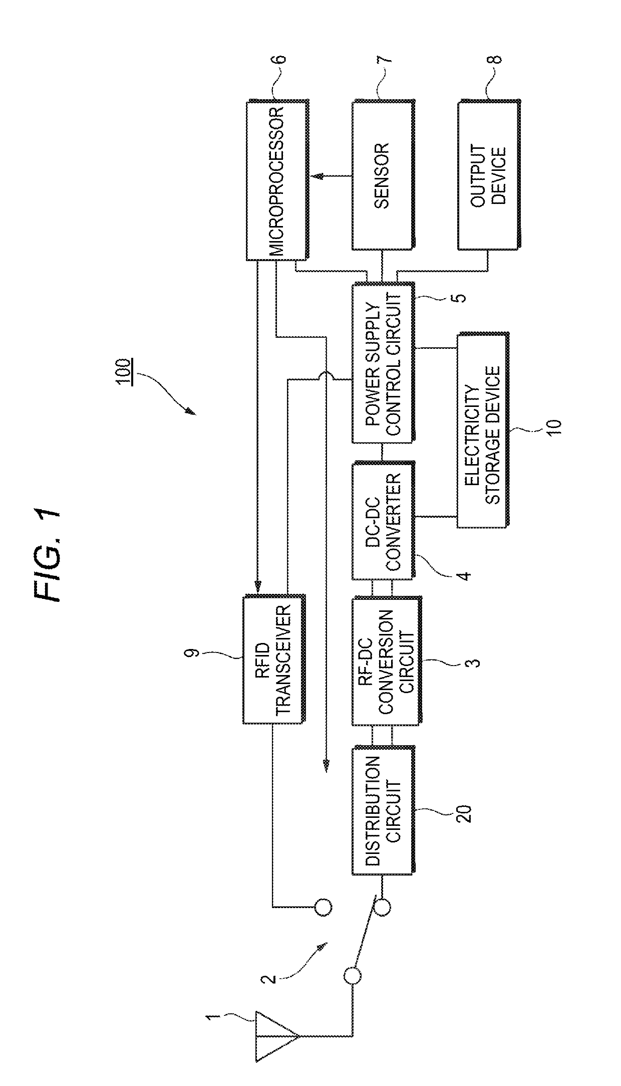
[0022]An energy harvest terminal 100 according to a preferred embodiment of the disclosure will be hereinafter described in detail with reference to the drawings.

[0023]FIG. 1 is a block diagram of the en...


PUM


Abstract

An energy harvest terminal includes a distribution circuit that distributes input radio wave power to at least two branch paths, a main rectification circuit that converts first radio wave power supplied to one of the at least two branch paths from the distribution circuit into DC output power, a DC-DC converter that performs voltage conversion on the DC output power of the main rectification circuit, a sub-rectification circuit that converts second radio wave power supplied to another of the at least two branch paths from the distribution circuit into DC output power, and an electricity storage device connected to an output of the DC-DC converter. The DC-DC converter performs a feedback control for equalizing an output voltage of the main rectification circuit and an output voltage of the sub-rectification circuit.

Description

CROSS REFERENCE TO RELATED APPLICATIONS[0001]This application is based on Japanese Patent Application (No. 2018-068036) filed on Mar. 30, 2018, the contents of which are incorporated herein by reference.BACKGROUND OF THE INVENTION1. Field of the Invention[0002]The present disclosure relates to an energy harvest terminal.2. Description of the Related Art[0003]At present, in sensor terminals employed in a wireless sensor network, a primary battery such as a button battery, a solar cell, a thermoelectric conversion element, or the like is used as a power source. However, primary batteries need to be replaced and solar cells and thermoelectric conversion elements are high in material cost. Such problems relating to the power source are obstacles to the spread of wireless sensor networks.[0004]Where RFID (Radio-Frequency Identification) is used as a communication system, sensor terminals do not transmit communication radio waves spontaneously and hence are low in power consumption. As su...

Claims


Application Information

Patent Timeline
IPC IPC(8): H02J7/34G05F1/67H02M3/04H02J7/00
CPCH02J7/345H02M3/04H02J7/0068G05F1/67H02J50/001H02J50/20H04B5/0031H04B5/0037H04B5/0062
Inventor TANAKA, YUKIHASABA, RYOSUKEKOYANAGI, YOSHIOKANAI, KAZUKI
Owner PANASONIC INTELLECTUAL PROPERTY MANAGEMENT CO LTD
Why Eureka
Try Eureka