Composite underbody structure for vehicles

a technology for underbody structures and vehicles, applied in the direction of understructures, vehicle components, superstructure subunits, etc., can solve the problems of large quantity of metal components in typical underbody assemblies, and be relatively heavy, so as to improve performance, reduce complexity, and increase thickness

Inactive Publication Date: 2019-10-10
CONTINENTAL STRUCTURAL PLASTICS INC +1
View PDF0 Cites 12 Cited by
  • Summary
  • Abstract
  • Description
  • Claims
  • Application Information

AI Technical Summary

Benefits of technology

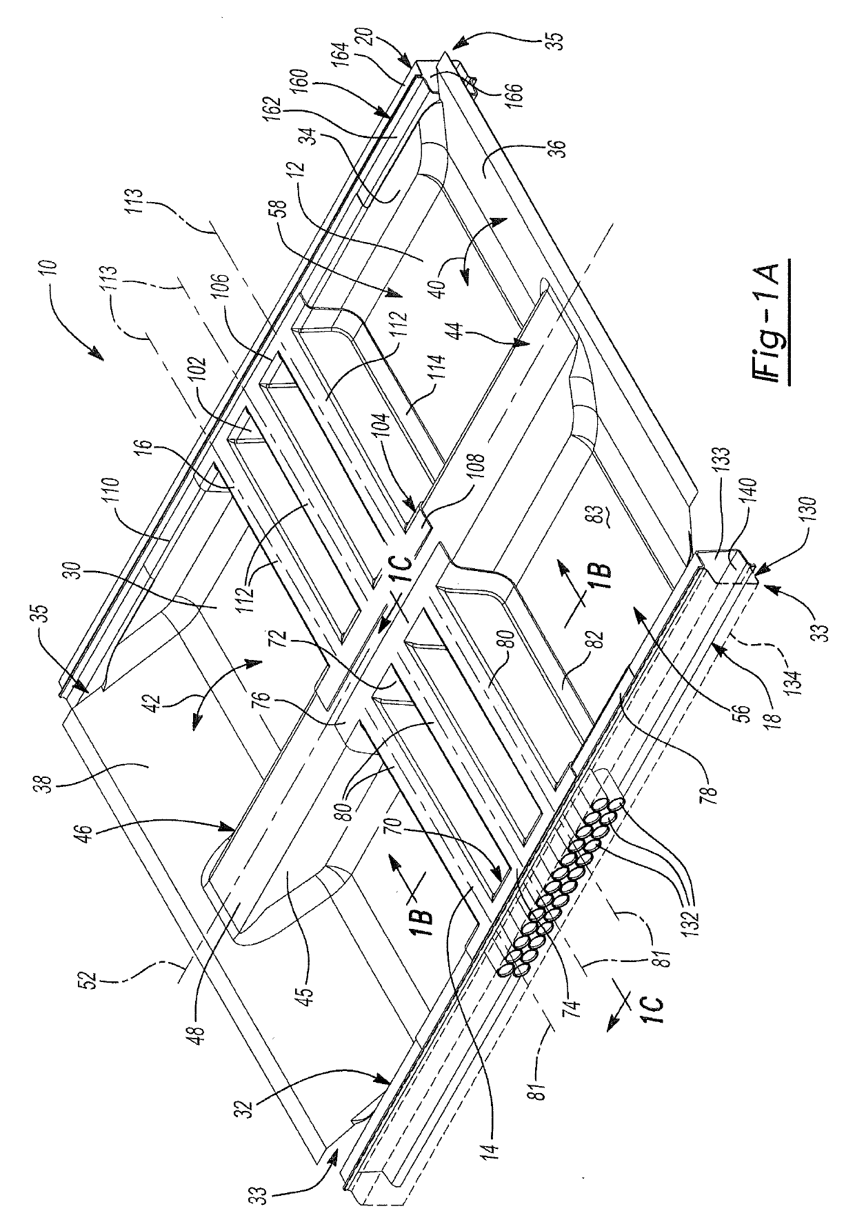
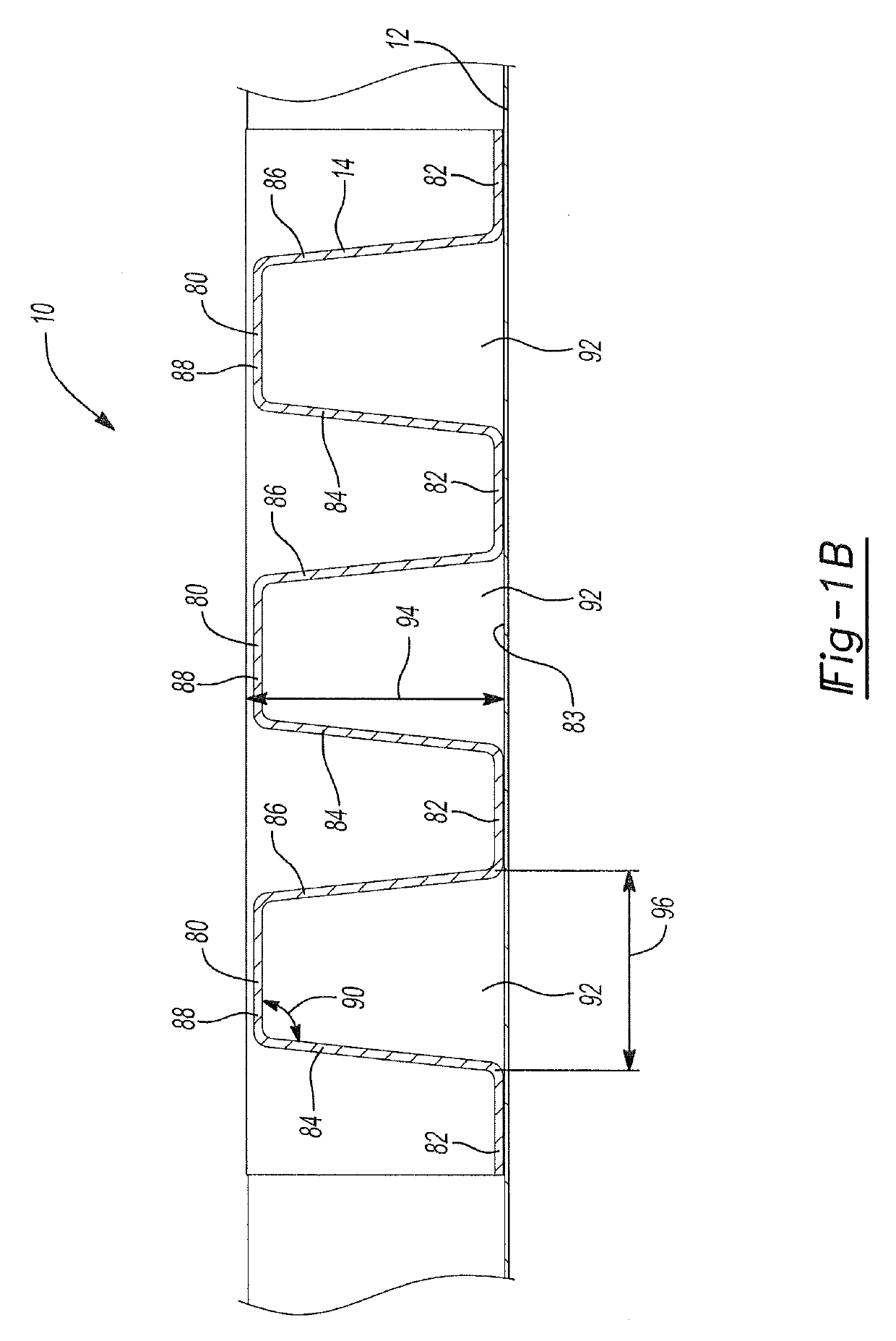
[0048]In various aspects, the present disclosure provides an underbody assembly for a vehicle that consists essentially of polymer-fiber composite components (the “composite underbody assembly”). The composite underbody assembly may generally include a base and a reinforcement. The base may be disposed on the underside of the vehicle and may include a first side and a second side opposite the first side. The base may extend in a longitudinal direction between a front of the vehicle and a rear of the vehicle. The reinforcement may be coupled to the base to provide additional structural support and improve performance during a side impact. The reinforcement may include an elongated ridge and an elongated trough. The elongated ridge and the elongated trough may be disposed adjacent to one another and may each extend transversely between the first side of the base and the second side of the base.
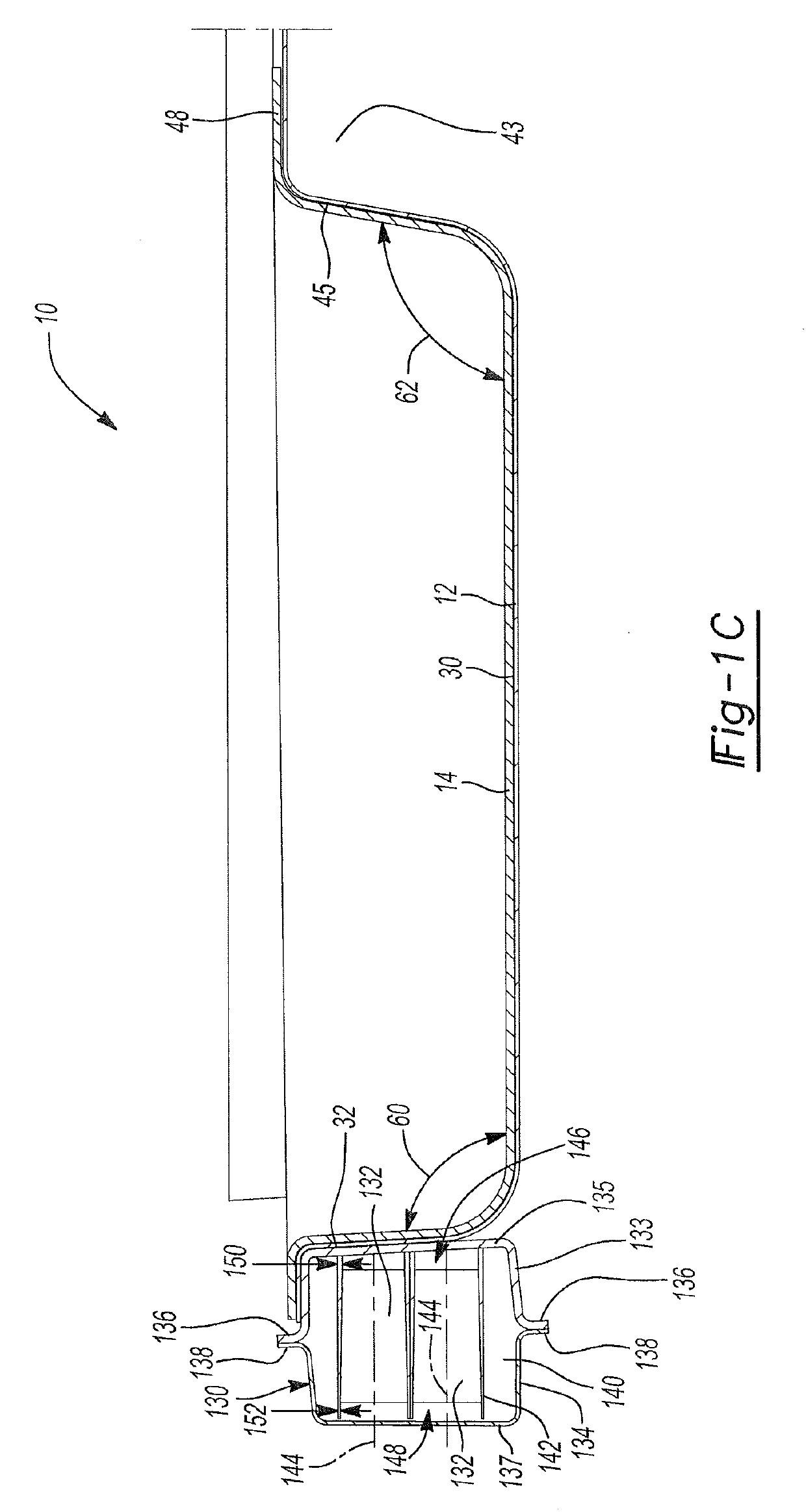
[0049]The composite underbody assembly may generally be less complex than the metal underbody assembly, including far fewer components (e.g., a nine-component composite underbody assembly may include: a base; first and second reinforcements; and first and second rocker assemblies having three components each). The base, the reinforcements, and / or the rocker assemblies may include walls defining a variable thickness, such as an increased thickness at regions of high expected stress. The composite underbody assembly may also include a rocker subassembly disposed at each side, each rocker subassembly having a housing and one or more internal energy-absorbing elements. The base, reinforcements, housings, and energy-absorbing elements may all be formed from or include a polymer-fiber composite material. The polymer-fiber composite components may be joined to one another with adhesive to minimize stress concentration at joints and reduce a quantity of components (e.g., eliminate or reduce a quantity of fasteners).
[0050]In certain aspects, the composite underbody assembly of the present disclosure may be light weight compared to the metal underbody assembly. The ability to form composite structures with variable thickness may facilitate consolidation of structural components. For example, where the typical metal underbody assembly includes distinct reinforcing components at each high stress area, the composite underbody assembly of the present disclosure may instead define regions of increased thickness at the high-stress areas. Thus, thickness can also be minimized at lower stress regions for additional weight reduction.
[0051]In contrast to the metal-and-composite underbody assembly, the composite underbody assembly of the present disclosure may consist essentially of polymer-fiber composite components such that it is free of metal structural components. The composite underbody assembly may exhibit sufficient side impact strength without the inclusion of metal structural members because of the thickened regions and / or the composite reinforcements having the transverse ridges. The components of the composite-intensive design may be fabricated in high-volume composite manufacturing processes. The decreased quantity of components compared to typical underbody designs (e.g., the metal underbody assembly or the metal-and-composite underbody assembly) may also lead to a relatively simple assembly process.

Problems solved by technology

Typical underbody assemblies may include a large quantity of metal components and be relatively heavy.

Method used


Image

  • Composite underbody structure for vehicles
  • Composite underbody structure for vehicles
  • Composite underbody structure for vehicles

Examples


Embodiment Construction

[0038]Example embodiments are provided so that this disclosure will be thorough, and will fully convey the scope to those who are skilled in the art. Numerous specific details are set forth such as examples of specific compositions, components, devices, and methods, to provide a thorough understanding of embodiments of the present disclosure. It will be apparent to those skilled in the art that specific details need not be employed, that example embodiments may be embodied in many different forms and that neither should be construed to limit the scope of the disclosure. In some example embodiments, well-known processes, well-known device structures, and well-known technologies are not described in detail.

[0039]The terminology used herein is for the purpose of describing particular example embodiments only and is not intended to be limiting. As used herein, the singular forms “a,”“an,” and “the” may be intended to include the plural forms as well, unless the context clearly indicates...


PUM


Abstract

An underbody assembly for a vehicle includes a plurality of polymer-fiber composite components. The polymer-fiber composite components include a base and a first reinforcement. The base includes a first side and a second side. The base is configured to extend in a longitudinal direction between a front of the vehicle and a rear of the vehicle. The first reinforcement is coupled to the base. The first reinforcement includes a first elongated ridge and a first elongated trough. The first elongated trough is disposed adjacent to the first elongated ridge. The first elongated ridge and the first elongated trough each extend transversely between the first side of the base and the second side of the base. In various aspects, the underbody assembly consists essentially of the polymer-fiber composite components.

Description

GOVERNMENT SUPPORT[0001]This invention was made with government support under DE-FOA-0000991 awarded by the Department of Energy. The Government has certain rights in the invention.INTRODUCTION[0002]This section provides background information related to the present disclosure which is not necessarily prior art.[0003]The present disclosure relates to a composite underbody structure for vehicles.[0004]Vehicle underbody assemblies provide structural support and mounting locations for other vehicle components. Underbody assemblies may include or be coupled to energy-absorbing components, such as rocker assemblies on opposing sides of the vehicle. Typical underbody assemblies may include a large quantity of metal components and be relatively heavy. However, it is advantageous that components of automobiles or other vehicles be lightweight to improve fuel efficiency. Thus, vehicle components, such as underbody assemblies, that exhibit both adequate strength during normal service and ener...

Claims


Application Information

Patent Timeline
Patent Type & Authority Applications(United States)
IPC IPC(8): B62D25/20B62D29/04B62D21/15
CPCB62D25/20B62D29/041B62D21/02B62D21/15B62D21/157
Inventor AITHARAJU, VENKATESHWAR R.AASHAT, SATVIRRODGERS, WILLIAM R.HOLINESS-STALLING, TERESA U.TOITGANS, MARC-PHILIPPEBURLEY, ADAM
Owner CONTINENTAL STRUCTURAL PLASTICS INC
Why Eureka
Try Eureka