
System and method for magnetic resonance mapping of physical and chemical changes in conducting structures

a technology of magnetic resonance mapping and physical and chemical changes, applied in the field of magnetic resonance mapping of physical and chemical changes in conducting structures, can solve the problems of slow battery technology progress, unforeseen setbacks, and difficulty in tracking defects inside the cells during operation in a non-destructive fashion

Pending Publication Date: 2019-10-10
NEW YORK UNIV
View PDF1 Cites 1 Cited by
  • Summary
  • Abstract
  • Description
  • Claims
  • Application Information

AI Technical Summary

Benefits of technology

This patent describes a method for diagnosing internal characteristics of a conducting structure, such as a battery, using an electromagnetic signal. The conducting structure is placed in a magnetic field and a detection medium is placed at a distance from it. The detection medium is then excited using an electromagnetic signal of one frequency, and an electromagnetic signal of a different frequency is received from the detection medium. The method measures changes in the frequency distribution of the detection medium to infer information about the conducting structure. The system includes an NMR / MRI magnet, a radiofrequency coil, a holder for the conducting structure, and containers for the detection medium. The overall field map is calculated by acquiring an NMR chemical shift spectrum and fitting it against a calculated susceptibility distribution. The technical effect is a method for non-destructive diagnosis of internal characteristics of a conducting structure.

Problems solved by technology

Continued demand for batteries with high energy capacity and the desire to quickly charge and discharge the devices present a number of formidable engineering and scientific challenges.
Several industry leaders have experienced unforeseen setbacks due to battery and cell malfunctions (e.g., swelling issues).
One major reason for the recurrence of such problems, and for the slow progress in battery technology is the difficulty in tracking defects inside the cells during operation in a nondestructive fashion.
Studying commercial battery designs under their typical operating conditions using conventional analytical tools has proven to be very difficult due to the large size, complicated structure and material properties of these devices.
Due to these limitations, most studies have been restricted to specialized cell designs with properties amenable to study using specific techniques.
These restrictions have meant that the investigation of performance and failure mechanisms in batteries is still performed destructively by cycling multiple cells and taking them apart at critical points to analyze changes that have occurred.
This process involves considerable time, effort and expense.
Moreover, physical and chemical changes occurring when the cell is taken apart can compromise any information obtained.
X-Ray CT is a successful technique for scanning electrochemical cells, but it is relatively slow, and thus usually not applicable for high throughput or in situ applications.
Furthermore, X-Ray CT provides diagnostics mostly of the denser components of a cell, and does not offer insights into subtle chemical or physical changes of the materials inside.
The prospect of applying magnetic resonance techniques (e.g., NMR and MM) to commercial batteries is restricted because under typical operating conditions, conductors are not transparent to radiofrequency (rf) irradiation.
In addition, the electrodes preclude the use of conventional MR for realistic or commercial-type cell geometries.

Method used


Image

  • System and method for magnetic resonance mapping of physical and chemical changes in conducting structures
  • System and method for magnetic resonance mapping of physical and chemical changes in conducting structures
  • System and method for magnetic resonance mapping of physical and chemical changes in conducting structures

Examples


Embodiment Construction

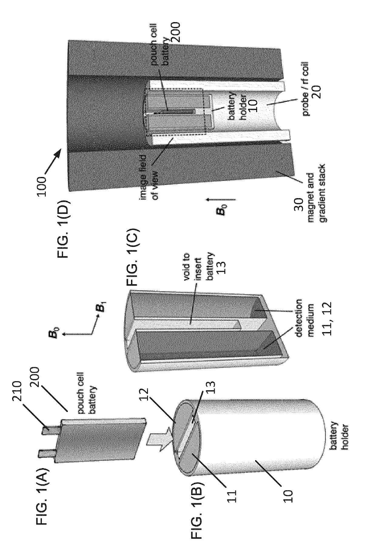
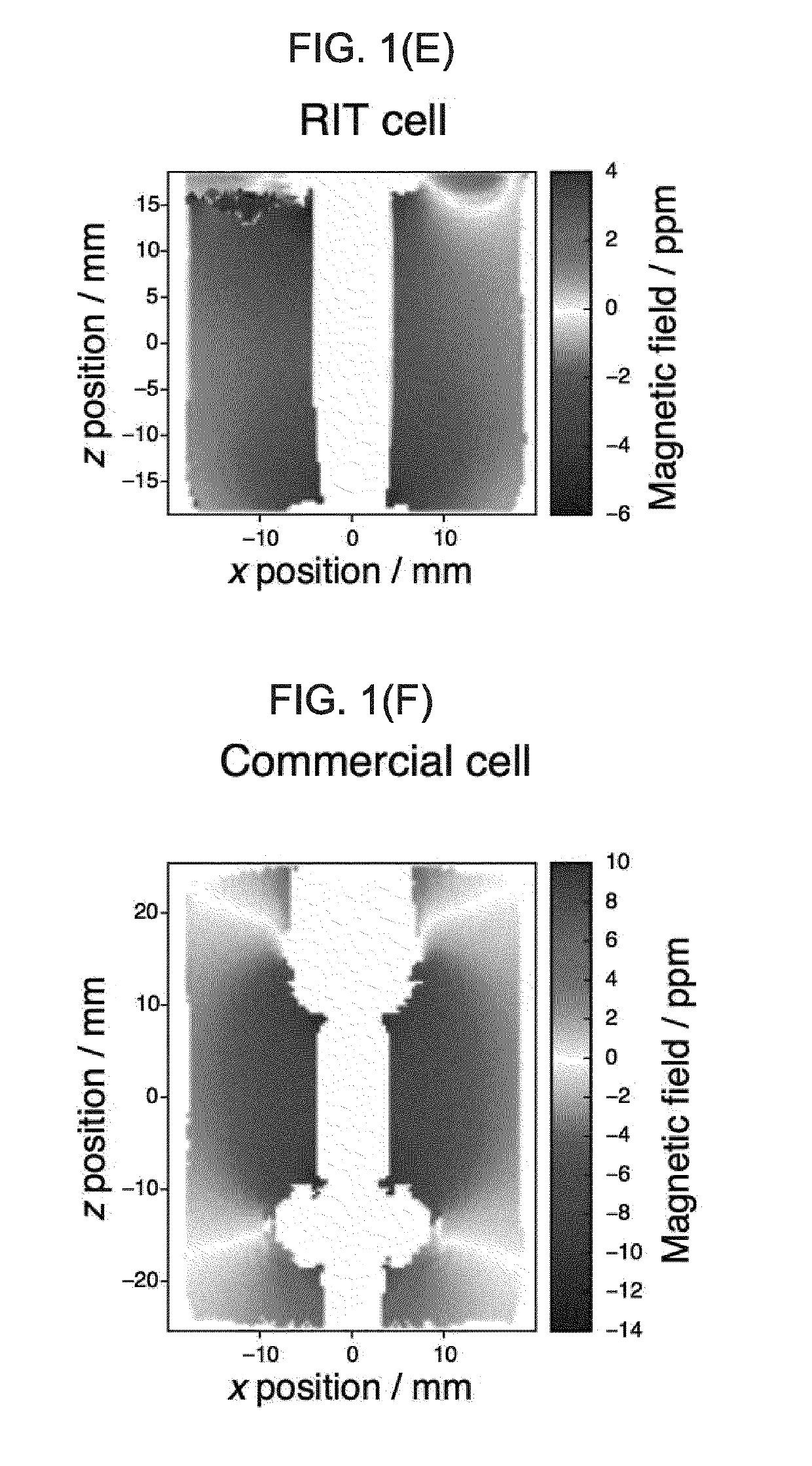
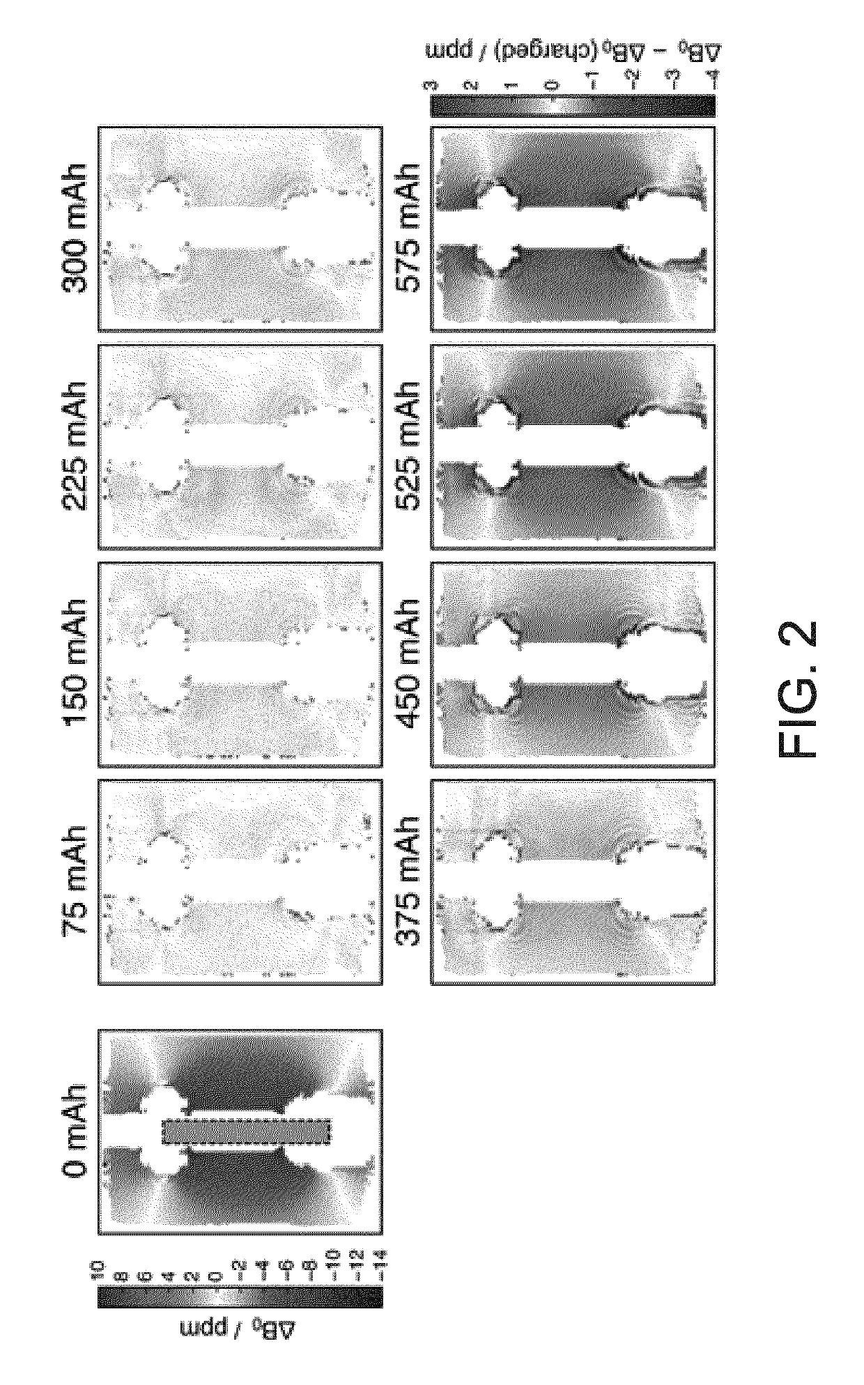
[0055]In general, the system and method described in this application relate to indirectly detecting the conductivity distribution and the distribution of magnetic susceptibility of conducting structures by measuring the space around it with NMR spectroscopy or MRI. In the embodiments described in this application, the conducting structure is a battery. However, the present application is not limited in this regard. The conducting structure may be, for example, a capacitor, a supercapacitor, a fuel cell, a catalyst material, etc. The system and method described herein provides cell diagnostics without requiring rf access to the inside of the cell. The method is based on imaging the induced or permanent magnetic field produced by the cell, and connecting it with processes occurring inside the cell. A method of diagnosing a battery includes providing the battery in a magnetic field, immersing the battery in a detection medium, or placing a detection medium in the vicinity of the batte...


PUM


Abstract

A method of diagnosing a conducting structure includes providing the conducting structure in a magnetic field, immersing the conducting structure in a detection medium, or placing a detection medium in the vicinity of the conducting structure, exciting nuclear or electronic spins within the detection medium using a broad-band excitation pulse, receiving an NMR or ESR spectrum from the detection medium, obtaining a frequency distribution of the detection medium, and indirectly measuring internal characteristics of the conducting structure by characterizing frequency changes in the frequency distribution. Conducting structures are analyzed on the basis of changes in magnetic susceptibilities and internal electric current distributions, which may change over the course of a charging / discharging cycle, and a result of degradation and failure of the conducting structure. The conducting structure may be, for example, a battery, a capacitor, a supercapacitor, a fuel cell, or a catalyst material.

Description

CROSS-REFERENCE TO RELATED APPLICATIONS[0001]This application is a continuation-in-part of International Application No. PCT / US2017 / 064948 filed Dec. 6, 2017, which claims priority to U.S. Provisional Application No. 62 / 431,075 filed Dec. 7, 2016; and this application is a continuation-in-part of U.S. patent application Ser. No. 15 / 785,284 filed Oct. 16, 2017, which claims priority to U.S. Provisional Application No. 62 / 431,075 filed Dec. 7, 2016 and is a continuation-in-part of International Application No. PCT / US2016 / 027624 filed Apr. 14, 2016, which claims priority to U.S. Provisional Application No. 62 / 149,159 filed Apr. 17, 2015. All of the above applications are incorporated herein by reference in their entirety for all purposes.FIELD OF THE INVENTION[0002]This application generally relates to detecting physical and chemical changes in conducting structures. In particular, this application relates to using magnetic resonance to indirectly measure internal characteristics of a ...

Claims


Application Information

Patent Timeline
IPC IPC(8): G01N24/08G01N24/10G01R33/56G01R31/36
CPCG01R33/5608G01N24/08G01N24/10G01R33/5602G01R31/3644G01R33/4816G01R33/443G01R31/36
Inventor JERSCHOW, ALEXEJILOTT, ANDREW J.MOHAMMADI, MOHADDESESILLETTA, EMILIAROMANENKO, KONSTANTIN
Owner NEW YORK UNIV
Learn More