Exhaust line, exhaust gas purification device, and purification device manufacturing process

Active Publication Date: 2019-10-17
FAURECIA SYST DECHAPPEMENT
View PDF0 Cites 12 Cited by
  • Summary
  • Abstract
  • Description
  • Claims
  • Application Information

AI Technical Summary

Benefits of technology

[0010]The heating plate is rigid enough to be fastened only by its edges. The plate is not required to bear fasteners distributed over its entire surface. Mounting is therefore made easier. Furthermore, it becomes possible to use a ceramic purification member, since the latter is no longer required to bear the fasteners of the heating member.
[0011]The use of branches extending in a spiral fro

Problems solved by technology

This does not promote heat transfer from the heating member to the exhaust gases.
Furthermore, the heating member is not very rigid, and must be fastened at multiple points on the purification member.
Th

Method used


Image

  • Exhaust line, exhaust gas purification device, and purification device manufacturing process
  • Exhaust line, exhaust gas purification device, and purification device manufacturing process
  • Exhaust line, exhaust gas purification device, and purification device manufacturing process

Examples


Example

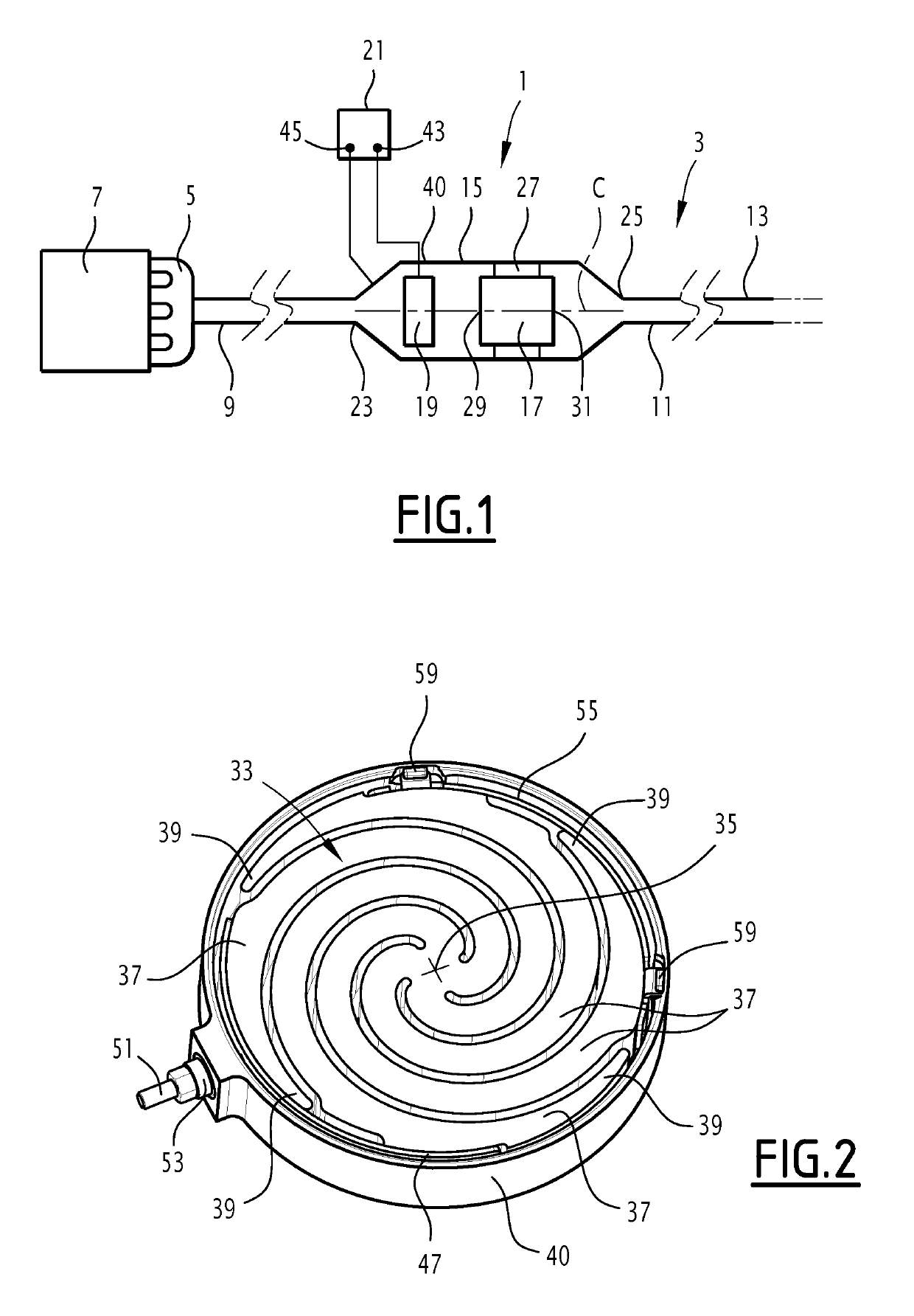
[0033]The purification device 1 schematically shown in FIG. 1 is provided to purify exhaust gases from a vehicle, typically exhaust gases from a car or truck.

[0034]It is inserted in the exhaust line 3 of the vehicle. The latter comprises an exhaust manifold 5 collecting the exhaust gases leaving combustion chambers of the heat engine 7 of the vehicle.

[0035]The purification device 1 is fluidly connected to the manifold 5 by an upstream pipe 9, on which other pieces of equipment are typically inserted, such as a turbocompressor.

[0036]In the downstream direction, the purification device 1 is fluidly connected by a downstream pipe 11 to a nozzle 13. Other pieces of equipment, such as mufflers or other purification equipment, are inserted between the purification device 1 and the nozzle 13. The purified exhaust gases are released into the atmosphere through the nozzle 13.

[0037]The purification device 1 comprises a tubular enclosure 15 having a central axis C, a purification member 17 for...


PUM

PropertyMeasurementUnit
Thicknessaaaaaaaaaa
Thicknessaaaaaaaaaa
Angleaaaaaaaaaa

Abstract

An exhaust gas purification device for a vehicle includes a tubular enclosure having a central axis, a purification member for exhaust gases housed in the tubular enclosure, an electric heating member housed in the tubular enclosure, and a power source electrically powering the electric heating member. The electric heating member comprises a heating plate made from an electrically conductive material extending in a plane substantially perpendicular to the central axis. The heating plate has a solid center and at least two branches, each branch extending in a spiral from the solid center to a free end located near the tubular enclosure. The heating plate is permeable to the exhaust gases and comprises a network of passages for the exhaust gas generating a turbulent flow of the exhaust gases through the heating plate.

Description

CROSS-REFERENCE TO RELATED APPLICATIONS[0001]This application is a U.S. non-provisional application claiming the benefit of French Patent Application No. 18 53167, filed on Apr. 11, 2018, which is incorporated herein by its entirety.FIELD OF INVENTION[0002]The present invention relates to vehicle exhaust gas purification devices, equipped with heating members.BACKGROUND OF THE INVENTION[0003]It is possible to make the heating member by using metal sheets, superimposed parallel to one another and rolled, as proposed by DE102007010758.[0004]Such a heating member channels the exhaust gases in a laminar flow. This does not promote heat transfer from the heating member to the exhaust gases.[0005]Furthermore, the heating member is not very rigid, and must be fastened at multiple points on the purification member. These fastening points are typically rods secured to the heating member and engaged in the channels of the purification member. This makes the use of a ceramic purification membe...

Claims


Application Information

Patent Timeline
IPC IPC(8): F01N3/20B01D53/94F01N3/027B01D46/00F01N3/28
CPCB01D53/94B01D46/0063F01N3/027F01N2240/16B01D46/0027F01N3/2803F01N3/2013F01N2510/06Y02A50/20Y02T10/12B01D46/84
Inventor OTTAVIANI, ERICBRUNEL, JEAN-PAUL
Owner FAURECIA SYST DECHAPPEMENT
Why Eureka
Try Eureka