Battery safety card

a lithium-ion battery and safety card technology, applied in secondary cell servicing/maintenance, batteries, instruments, etc., can solve the problems of lithium-ion batteries presenting a potential fire hazard, battery fire hazards, and other hazards

Active Publication Date: 2019-10-17
SLING MEDIA PVT LTD
View PDF4 Cites 5 Cited by
  • Summary
  • Abstract
  • Description
  • Claims
  • Application Information

AI Technical Summary

Benefits of technology

The present patent provides a system and method to disconnect a battery from a load circuit when the battery temperature is outside a selected range. The system includes multiple temperature sensors positioned on a printed circuit board, with one sensor on the battery and another on the load circuit. The temperature sensors are connected to a printed circuit board with temperature pads, which are thermally coupled to the battery. The system also includes logic circuits that receive the output from the temperature sensors and generate an error signal if there is a temperature outside the selected range. The system can disconnect the battery from the load circuit simultaneously or sequentially, with the battery charge logic circuit and voltage regulators being disabled first, followed by the battery supply switch circuit and battery charge logic circuit. The system can also use different techniques and sources for the temperature sensors to reduce the likelihood of failure. The technical effect of this patent is to provide a reliable and flexible system for protecting battery and load circuits from damage caused by high or low battery temperatures.

Problems solved by technology

Lithium-ion batteries present a potential fire hazard if they reach certain temperature conditions, whether too high of a temperature or too low of a temperature.
Hazards can also arise if charging or discharging of the battery occurs with the battery is above or below a selected temperature.
Attempting to charge or discharge the battery at too high of voltage or current can also create problems.
Mechanical abuse, such as physical pressure, and impact from an outside force may also cause fire hazards with a battery.

Method used


Image

  • Battery safety card
  • Battery safety card
  • Battery safety card

Examples


Embodiment Construction

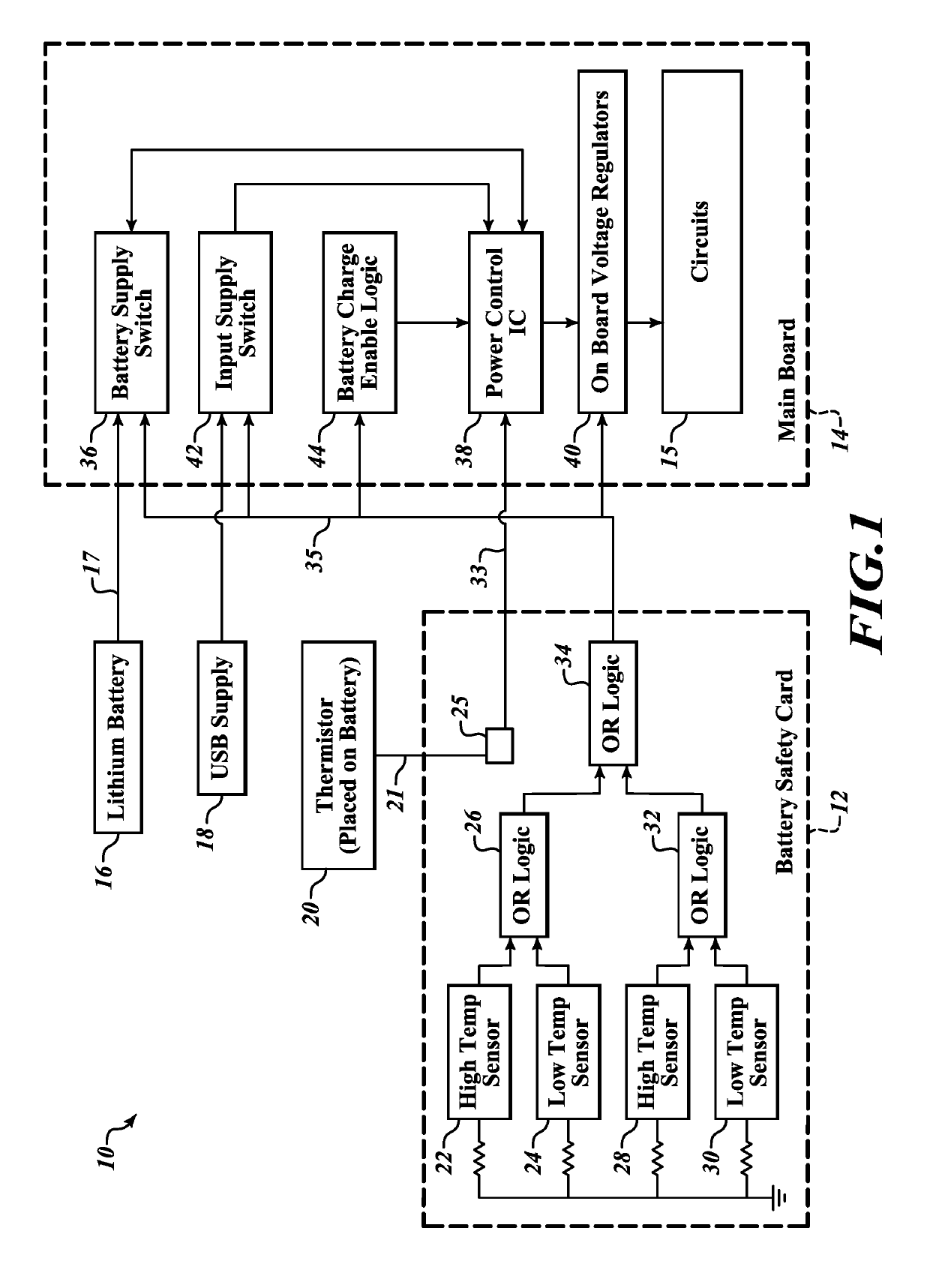
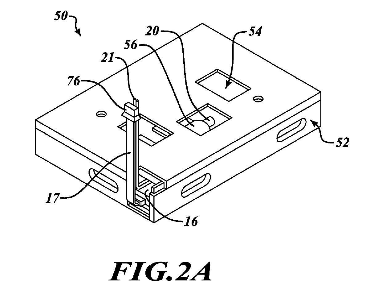
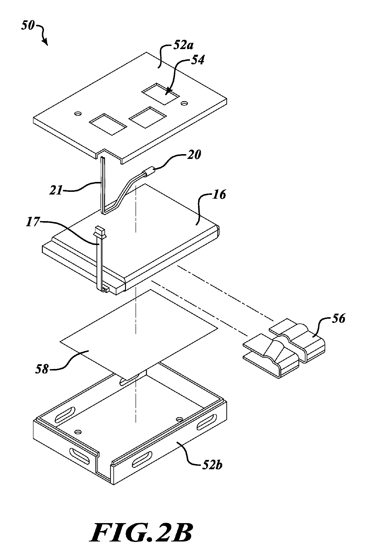
[0019]FIG. 1 illustrates a block diagram of a battery powered system 10 that includes a battery safety card 12, a main board 14, a lithium-ion battery 16, a USB port 18, and circuits 15 that are the load driven by the battery.

[0020]The battery safety card 12 includes a number of circuits mounted on a printed circuit board. These circuits include a first high temperature sensor 22 and a first low temperature sensor 24. The first high temperature sensor 22 and first low temperature 24 output the results of their temperature sense data to an OR logic gate 26. A second high temperature sensor 28 and a second low temperature sensor 30 output the results of their data to a second OR logic gate 32. The first OR gate 26 and the second OR gate 32 output their data signal to a third OR gate 34 that provides a temperature signal on output line 35. The battery provides power to the main board 14 on power output line 17.

[0021]The first high temperature sensor 22 senses the external temperature o...


PUM


Abstract

A system and method to disconnect a battery from a load circuit when the battery temperature is outside a selected high threshold or a low threshold. A plurality of temperature sensors are provided for sensing a high battery temperature and a low battery temperature. If the either the high temperature sensor or the low temperature sensor outputs an error signal, the battery is disconnected from the load circuits. The disconnection from the load circuits is carried out by disabling at least four different circuits, any one of which alone will disconnect the battery from the load circuits. These four circuits include a battery switch circuit, a power control circuit, a charge control logic circuit and a voltage regulator circuit. The plurality of temperature sensors provides a backup system in the event any one of the temperature sensors is defective.

Description

BACKGROUNDTechnical Field[0001]This disclosure is related to ensuring safe operation of a lithium-ion battery and, in particular, having safety switches and backup safety switches to disconnect the battery from the system under selected temperature conditions.Description of the Related Art[0002]Lithium-ion batteries present a potential fire hazard if they reach certain temperature conditions, whether too high of a temperature or too low of a temperature. Hazards can also arise if charging or discharging of the battery occurs with the battery is above or below a selected temperature. Attempting to charge or discharge the battery at too high of voltage or current can also create problems. Mechanical abuse, such as physical pressure, and impact from an outside force may also cause fire hazards with a battery. Accordingly, a circuit which reduces the chance of an unsafe temperature, whether high or low, of a lithium-ion battery due to many types of possible electrical or physical condit...

Claims


Application Information

Patent Timeline
IPC IPC(8): H02J7/00G01K13/00H02H7/18H01M10/0525H01M10/48H01M10/44H01M10/42
CPCH02J7/0031H01M10/425H01M2010/4271G01K13/00H01M10/486H01M10/443H01M10/0525H02J7/0068H02H7/18H01M2200/10H01M2010/4278H02H5/04H02J7/00309H02J7/007194Y02E60/10
Inventor PK, ARUN
Owner SLING MEDIA PVT LTD
Why Eureka
Try Eureka