Dual-rectification full bridge interleaved single stage pfc converter circuit and control methods thereof

a converter circuit and power factor technology, applied in the direction of electric variable regulation, process and machine control, instruments, etc., can solve the problems of reducing so as to save individual pwm pfc control circuits and improve the efficiency of pcb control circuits , the effect of excellent active power factor correction performan

Active Publication Date: 2019-10-24
SHANGHAI TUITUO TECH CO LTD
View PDF0 Cites 11 Cited by
  • Summary
  • Abstract
  • Description
  • Claims
  • Application Information

AI Technical Summary

Benefits of technology

[0047]The disclosed invention of converter comprising interleaved boost circuit, can achieve excellent active power factor correction performance. The converter takes use of two switching components of the full bridge converter to alternately drive two boost inductors, which eliminates the use of two boost switching components and two boost rectifiers required in a conventional interleaved boost PFC circuit, and saves individual PWM PFC control circuit. Furthermore, the two boost inductors are designed to operate at a discontinuous mode (DCM), which enables the four switching components of the full bridge converter to operate at zero voltage switching (ZVS) state to reduce switching loss. The dual-rectification circuit makes it possible to allocate inrush current limiter at a position that can inhibit inrush current at power supply turn-on but has no loss during the subsequent normal operation. As a result, this circuit greatly saves cost, saves space, increases efficiency and removes heat from power supply so that low cost, compact, high efficiency power supply is achieved.

Problems solved by technology

1. Need an individual PWM control circuit to improve power factor.
2. Need individual power supply circuits for PFC and PWM control circuits.
3. Need independent boost switching components (FETs and diodes) and PFC current sensing resistor R1.
4. Need PCB space, which is difficult in compact mechanical and layout design.
5. More components count, high cost.
6. Boost switching components Q1 and Q2 operate at hard switching mode, results in high loss, poor EMI noise.

Method used


Image

  • Dual-rectification full bridge interleaved single stage pfc converter circuit and control methods thereof
  • Dual-rectification full bridge interleaved single stage pfc converter circuit and control methods thereof
  • Dual-rectification full bridge interleaved single stage pfc converter circuit and control methods thereof

Examples


first embodiment

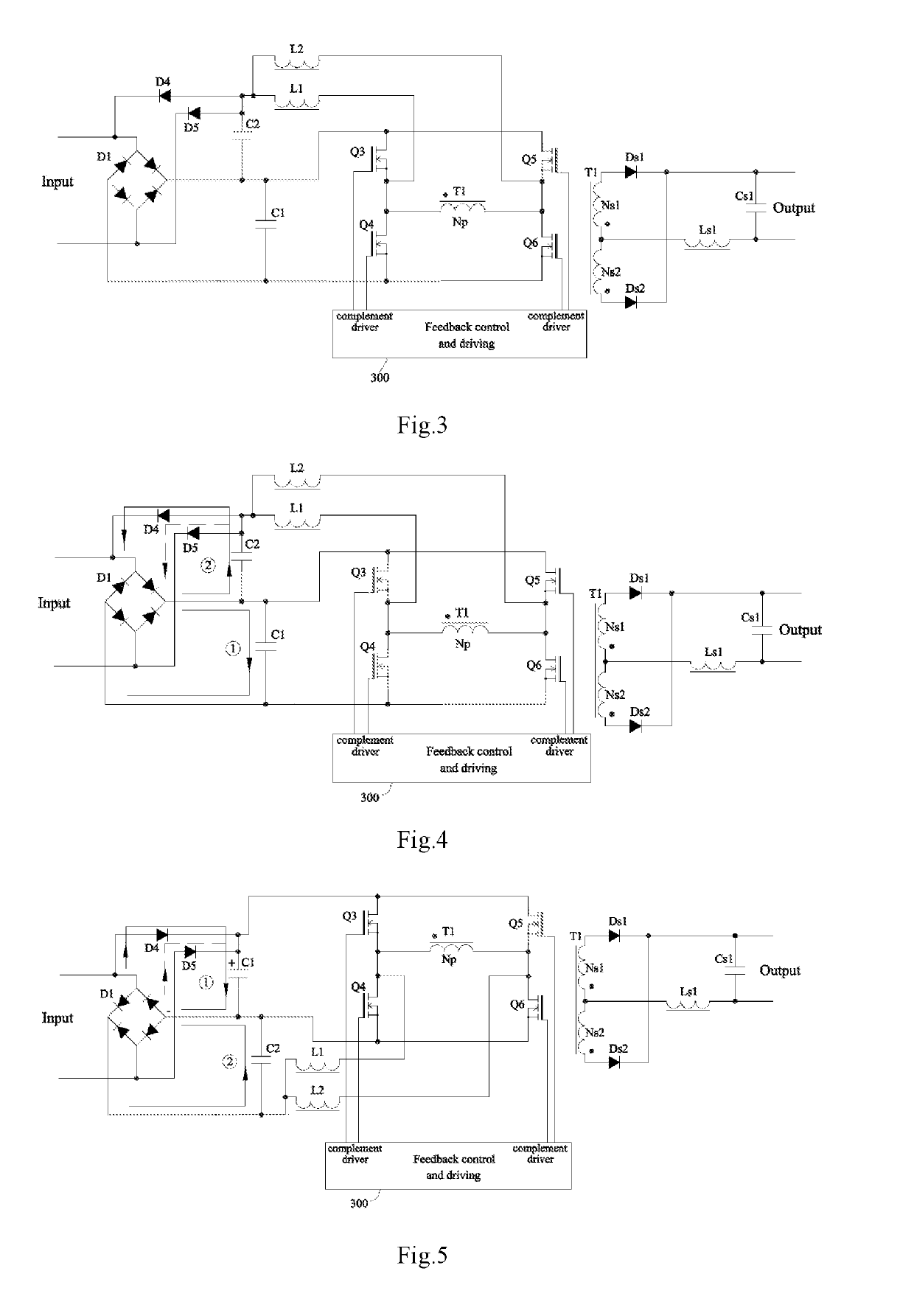
[0147]The power supply of first embodiment is designed in hard switching mode. As FIG. 3 shows, dual-rectification full bridge converter with interleaved single stage PFC is implemented as a combination of interleaved boost circuit and full bridge DC-DC converter. It comprises first and second input rectification circuits, storage capacitor C1, boost capacitor C2, interleaved boost converter circuit, and full bridge DC-DC converter circuit. In full bridge DC-DC converter, first switching component Q3 and second switching components Q4 are connected in series and form the first bridge arm; third switching component Q5 and fourth switching component Q6 are connected in series and form the second bridge arm. Both bridge arms are connected in parallel with storage capacitor C1. Q3, Q6 and Q4, Q5 alternately drive T1's primary winding. First inductor L1 and second inductor L2 are coupled to the center joints of first arm and second arm respectively and their other nodes coupled to boost ...

second embodiment

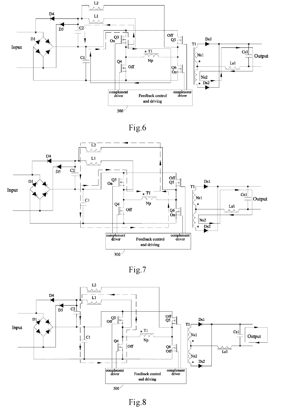
[0179]The operation introduced in second embodiment is soft switching mode. Soft switching technology takes use of resonant current to flow in switching component reversely, and discharges voltage on parasitic capacitor to near zero, so as to realize zero voltage switch-on at next conduction.

[0180]As shown in FIG. 17, difference between the second embodiment from the first embodiment is: D1, D4, D5 and storage capacitor C1 construct the first input rectification circuit. D1 and boost capacitor C2 construct the second input rectification circuit. Storage capacitor C1, boost capacitor C2 and output of first rectification circuit are coupled at their positive nodes.

[0181]Boost inductors L1 and L2 are designed at discontinuous current mode (DCM). C1, C2, L1 and on-state Q4 or Q5 construct resonant current loop, boost resonant current occurs after boost current's returning to zero at DCM, switching components Q4 or Q5's cut-off forces boost resonant current, after its returning to zero, ...

third embodiment

[0196]As shown in FIG. 25, between negative poles of storage capacitor C1 and first rectification component D1, an inrush current limiter device or circuit Rth1 is inserted to inhibit input surge current at turn-on of converter or EMC immunity test. Rth1 neither belongs to boost loop, nor belongs to second input rectification loop, so it only operates at power converter's turn-on. It is lossless after converter enters normal operation.

[0197]Operating principle is same as first embodiment (CCM) or second embodiment (DCM).


PUM


Abstract

An AC-DC converter with a dual-rectification full bridge interleaved single stage PFC circuit and its control method are disclosed. The converter uses two switching components of a full bridge converter to alternately drive two boost inductors, which eliminates the use of two boost switching components and two boost rectifiers required in a conventional interleaved boost PFC circuit, and also saves individual PWM PFC control circuit.

Description

CROSS-REFERENCE TO RELATED APPLICATION[0001]This application claims the priority of Chinese patent application number 201810370623.6, filed on Apr. 24, 2018, the entire contents of which are incorporated herein by reference.TECHNICAL FIELD[0002]The present invention relates to an AC-DC converter with a dual-rectification full bridge interleaved single stage power factor correction (PFC) circuit and its control methods.BACKGROUND[0003]Electrical equipment or appliance connected to AC power grid line should satisfy current harmonic standard IEC61000-3-2. As shown in FIG. 1, With regard to different equipment or applications, IEC61000-3-2 has correspondingly set different current harmonic limits, among which, a Class A limit is for normal electrical equipment, Class B for portable tools and non-professional welding equipment, Class C for lighting equipment, and Class D for portable personal computer, monitor and TV.[0004]Existing switching mode power supply technology, ranging from med...

Claims


Application Information

Patent Timeline
Patent Type & Authority Applications(United States)
IPC IPC(8): H02M1/42H02M3/335H02M1/08H02M7/06
CPCH02M1/4241H02M2001/0058H02M1/4258H02M3/33569H02M1/4225H02M3/156H02M7/2176H02M1/0058H02M3/33573H02M3/01Y02B70/10H02M3/1586
Inventor LI, RENHONGSHEN, ZHUO
Owner SHANGHAI TUITUO TECH CO LTD
Why Eureka
Try Eureka