
Locating a vehicle

a real-time, vehicle technology, applied in the direction of image enhancement, process and machine control, etc., can solve the problems of accumulating over time uncertainties and errors, methods that do not offer enough accuracy to achieve the application of augmented reality or partial, and cannot compensate for positioning uncertainties, type of approach, and calculation of relative displacement between images

Inactive Publication Date: 2019-10-31
COMMISSARIAT A LENERGIE ATOMIQUE ET AUX ENERGIES ALTERNATIVES
View PDF0 Cites 3 Cited by
  • Summary
  • Abstract
  • Description
  • Claims
  • Application Information

AI Technical Summary

Benefits of technology

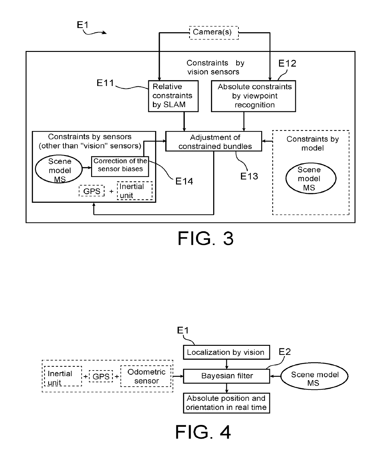
The invention provides a method for accurately and robustly localizing a vehicle using a combination of vision and other sensors. The method includes steps of determining relative and absolute visual constraints, adjusting constrained bundles, and performing Bayesian filtering. The system can use data from various sensors, such as the inertial unit, satellite navigation module, and odometric sensor, to produce accurate and precise vehicle localization in real-time. The technical effects of the invention include improved accuracy and reliability of vehicle localization, as well as improved efficiency and responsiveness of the vehicle localization system.

Problems solved by technology

These methods do not offer enough accuracy to be able to achieve an application of augmented reality or of partial or total automation of a vehicle driving.
Indeed, they rely mainly on the GPS sensor and do not compensate for the uncertainties of positioning of this sensor in the city due to the phenomena of multi-echoes, occlusions of part of the satellite constellation, or “canyon” effect.
This type of approach, calculating relative displacements between images, accumulates over time uncertainties and errors.
However, the viewpoint recognition module is very sensitive to the occlusions and robustness of the signature of the visual landmarks (weather-related variations, changes in lighting, seasons .
Thus, these methods do not provide sufficient robustness for an accurate absolute localization of a vehicle, for example for a long car journey.
This method relies on two relatively fragile modules and makes use of them alternately, which is not a real source of reliability.
However, an odometric sensor is known to drift over time for extrinsic (slips of the wheels on the ground) and intrinsic (time integration of a relative motion) reasons.
The GPS sensor, for its part, is known to encounter problems in urban areas (multi-echoes, occlusions of part of the satellite constellation, “canyon” effect).
Even with a very accurate GPS system, for example of the GPS-RTK type, it is very likely to encounter positioning errors of several meters in urban areas.

Method used


Image

  • Locating a vehicle
  • Locating a vehicle

Examples


Embodiment Construction

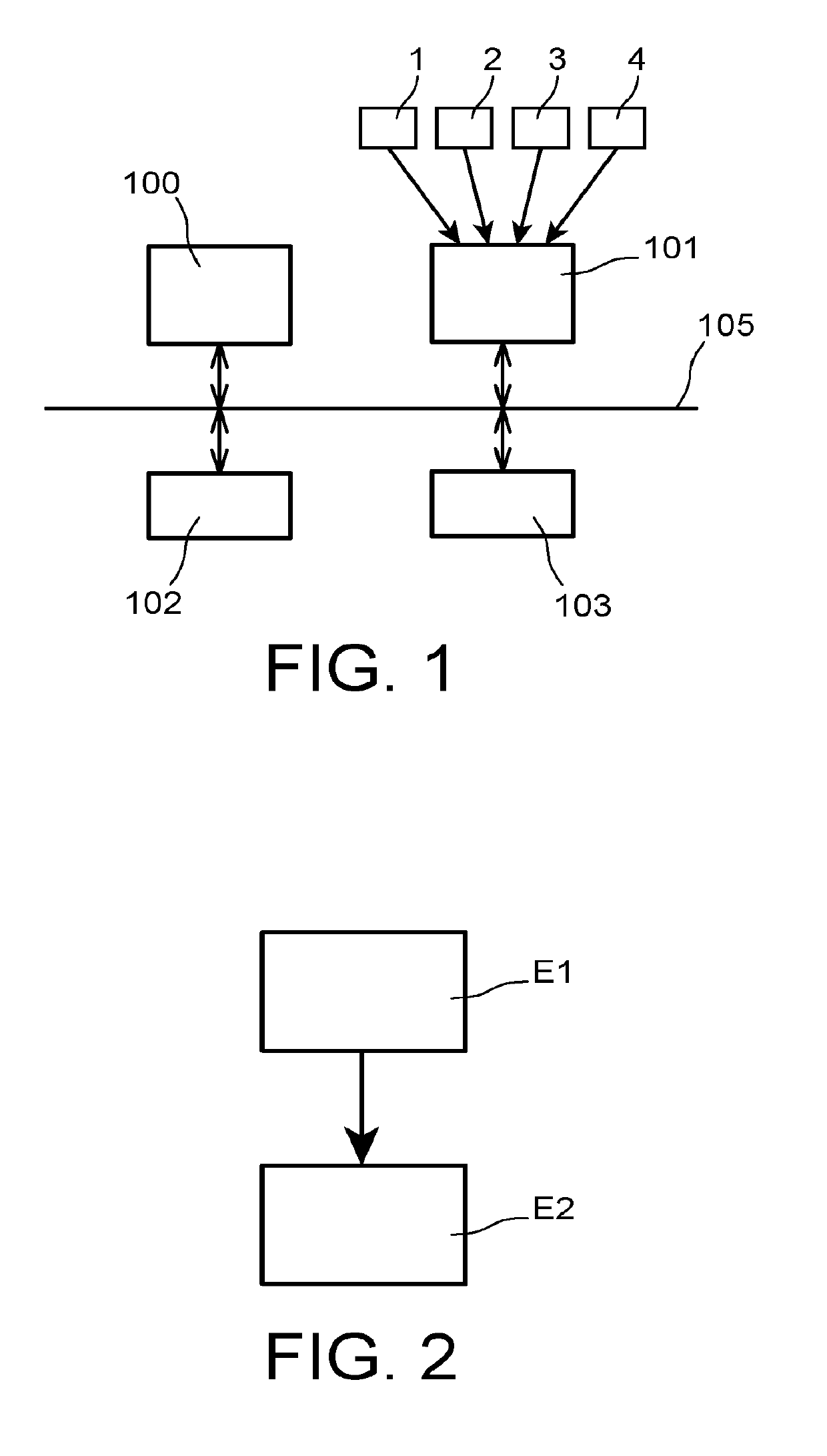
[0061]According to a preferred embodiment, represented in FIG. 1, a device for localizing a vehicle includes a set of sensors installed on the vehicle. These sensors are:[0062]at least one vision sensor 1 that provides image data of the vehicle environment,[0063]a satellite navigation module 2 called GNSS “Global Navigation Satellite System”,[0064]an odometric sensor 3, and[0065]an inertial unit 4.

[0066]In particular, the vision sensor 1 is a perspective monocular camera whose intrinsic parameters are known and fixed.

[0067]It should be noted that the satellite navigation module 2, the odometric sensor 3 and the inertial unit 4 constitute optional equipment. The vehicle localization device can therefore include only two of them, or only one of them. The satellite navigation module 2 is for example a GPS (Global Positioning System) module.

[0068]These sensors are connected to a data processing module that has the general structure of a computer. It includes in particular a processor 10...


PUM


Abstract

A method for locating a vehicle, including at least one vision sensor and at least one item of equipment from among an inertial navigation unit, a satellite navigation module and an odometry sensor. The method including carrying out vision-localization from image data supplied by the at least one vision sensor, to produce first location data, and applying a Bayesian filtering via a Kalman filter, taking into account the first location data, to the data derived from the at least one item of equipment and the data from a scene model, to produce second data for locating the vehicle.

Description

TECHNICAL FIELD[0001]The present invention relates to the localization in real time of a vehicle.[0002]The applications of the invention are, for example, the vehicle driving assistance, the autonomous driving or even the augmented reality.STATE OF THE PRIOR ART[0003]In the railway sector, localization modules presented in the article: “Simultaneous Localization and Mapping for Path-Constrained Motion” by Carsten Hasberg, Stefan Hensel, and Christoph Stiller, IEEE Transactions on intelligent Transportation Systems, Vol. 03, No. 2, June 2012, or in the article: “Bayesian Train Localization Method Extended By 3D Geometric Railway Track Observations From Inertial Sensors” by Oliver Heirich, Patrick Robertson, Adrian Cardalda Garcla and Thomas Strang, 2012, or also in the article: “RailSLAM—Localization of Rail Vehicles and Mapping of Geometric Railway Tracks” by Oliver Heirich, Patrick Robertson and Thomas Strang, IEEE International Conference on Robotics and Automation (ICRA), May 201...

Claims


Application Information

Patent Timeline
IPC IPC(8): G01C21/20G05D1/02G06T7/73G06K9/00G06K9/62
CPCG06T7/73G06T2207/30244G05D2201/0213G06T2207/30252G05D1/0274G05D1/0251G06K9/6201G01C21/20G06K9/00791G05D1/0272G06T7/70G06T7/579G06T7/246G06V20/56G06F18/22
Inventor DHOME, YOANNCARRIER, MATHIEUGAY-BELLILE, VINCENT
Owner COMMISSARIAT A LENERGIE ATOMIQUE ET AUX ENERGIES ALTERNATIVES
Learn More