
Gas sprayer for substrate treatment device, and substrate

a technology for processing equipment and substrates, applied in the direction of coatings, chemical vapor deposition coatings, plasma techniques, etc., can solve the problems of reducing substrate quality, increasing and reducing the density of plasma generated in the plasma area pa, so as to increase the efficiency of chemical reactions and reduce the consumption amount of process gas. , the effect of increasing the efficiency of the processing process

Inactive Publication Date: 2019-10-31
JUSUNG ENG
View PDF0 Cites 0 Cited by
  • Summary
  • Abstract
  • Description
  • Claims
  • Application Information

AI Technical Summary

Benefits of technology

The present invention aims to reduce the size of the plasma area in a substrate processing unit, which increases the efficiency of the chemical reaction and decreases the consumption of process gas, thereby reducing costs and improving quality. Additionally, the invention reduces the non-reaction process gas, which reduces the occurrence of particles and improves the quality of the substrate.

Problems solved by technology

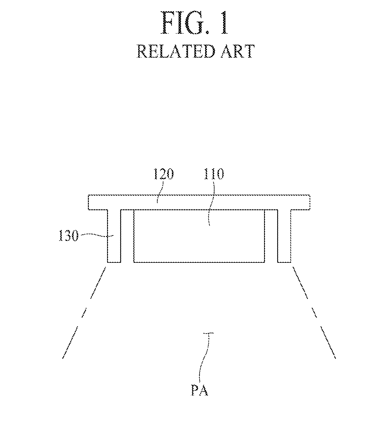
First, in the related art gas distribution apparatus 100, since the plasma area PA extends to the inner side of the first electrode 110 and the outer side of the first electrode 110, there is a problem where a density of the plasma generated in the plasma area PA is reduced.
Second, in the related art gas distribution apparatus 100, since the density of the plasma is reduced, a flow rate of a non-reaction process gas increases, and for this reason, there is a problem where a consumption amount of a process gas increases. Also, in the related art gas distribution apparatus 100, since the flow rate of the non-reaction process gas increases, the number of occurring particles increases, and for this reason, there is a problem where the quality of a substrate is reduced.

Method used


Image

  • Gas sprayer for substrate treatment device, and substrate
  • Gas sprayer for substrate treatment device, and substrate
  • Gas sprayer for substrate treatment device, and substrate

Examples


Embodiment Construction

[0028]Hereinafter, embodiments of a substrate processing apparatus according to the present inventive concept will be described in detail with reference to the accompanying drawings. A gas distribution apparatus for substrate processing apparatuses according to the present inventive concept may be included in a substrate processing apparatus according to the present inventive concept, and thus, will be described together while describing embodiments of the substrate processing apparatus according to the present inventive concept.

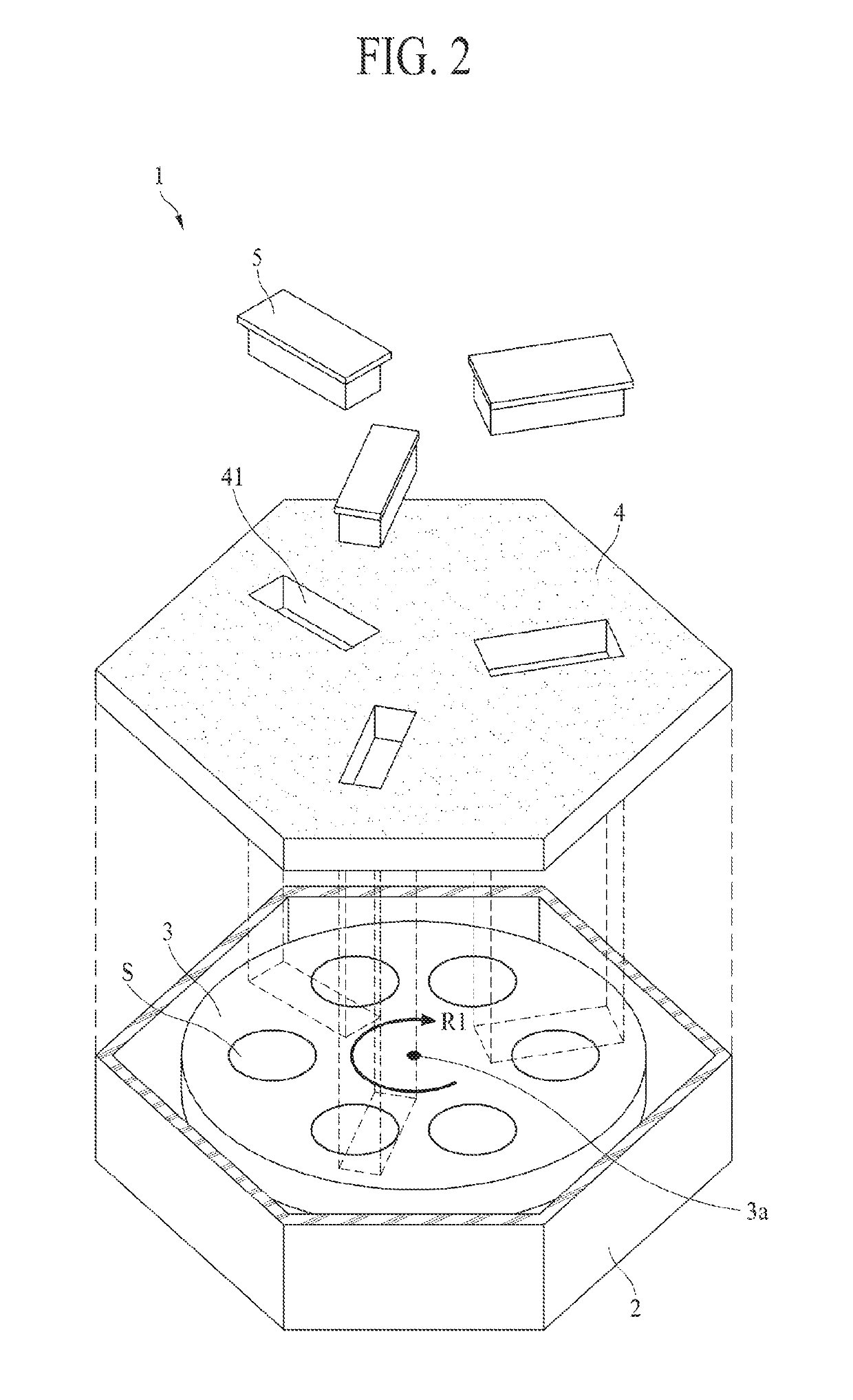
[0029]Referring to FIG. 2, a substrate processing apparatus 1 according to the present inventive concept performs a processing process on a substrate S. For example, the substrate processing apparatus 1 according to the present inventive concept may perform a deposition process of depositing a thin film on the substrate S. The substrate processing apparatus 1 according to the present inventive concept includes a process chamber 2 where the deposition process...


PUM

PropertyMeasurementUnit
frequencyaaaaaaaaaa
frequencyaaaaaaaaaa
frequencyaaaaaaaaaa

Abstract

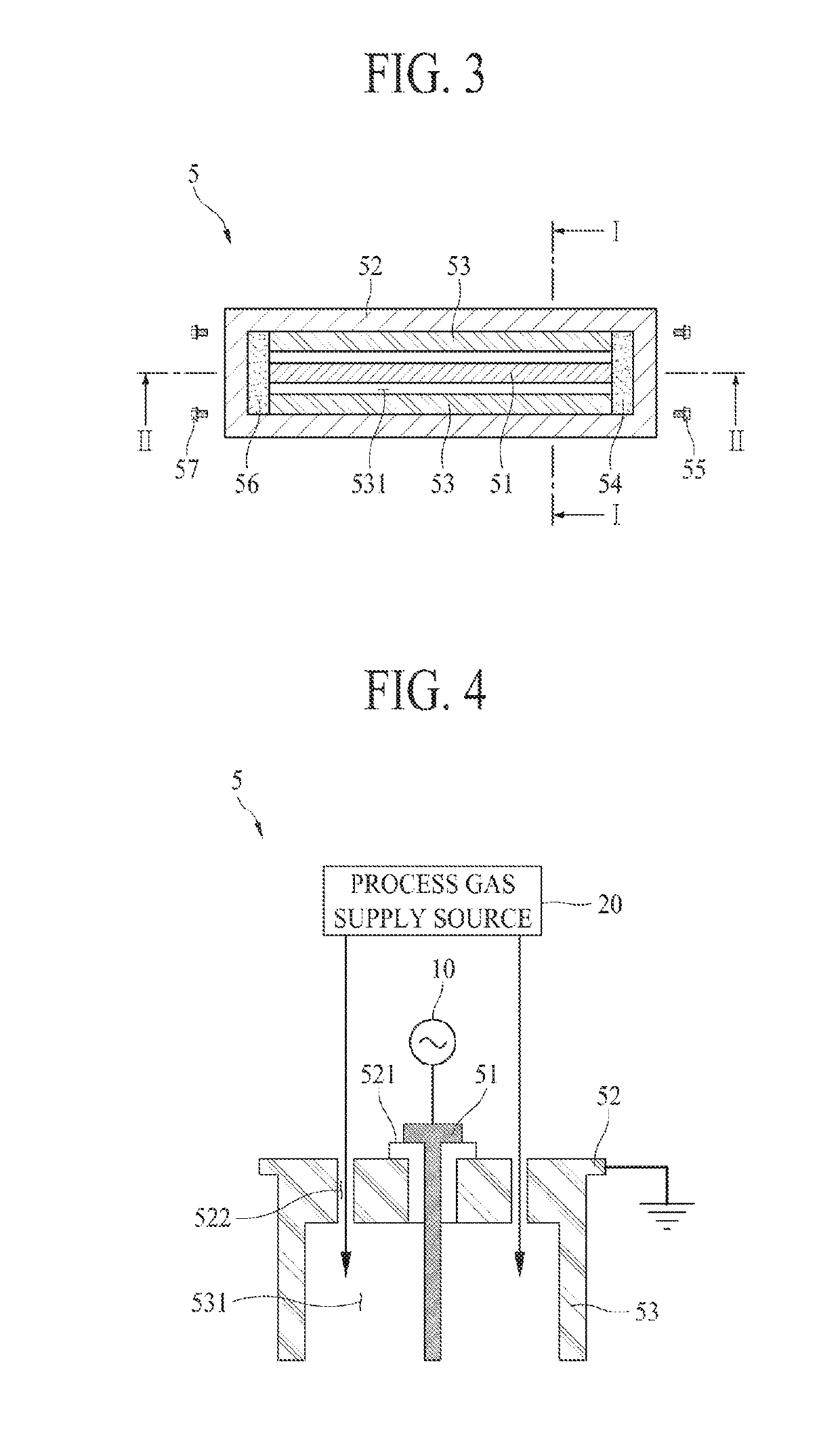
The present inventive concept relates to a substrate processing apparatus and a gas distribution apparatus for substrate processing apparatuses including: a plasma generator generating plasma for performing a processing process on a substrate supported by a substrate supporting unit; a ground body coupled to the plasma generator; and a plasma shield shielding the plasma generated by the plasma generator, wherein the plasma generator includes a first electrode for generating the plasma and a second electrode coupled to the ground body at a position spaced apart from the first electrode so that a gas distribution space for distributing a process gas is provided between the first electrode and the second electrode, and the plasma shield shields the plasma, generated by the plasma generator, in at least one of a top of the substrate and a bottom of the substrate.

Description

TECHNICAL FIELD[0001]The present inventive concept relates to a gas distribution apparatus for substrate processing apparatuses and a substrate processing apparatus, which perform a substrate processing process such as a deposition process of depositing a thin film on a substrate.BACKGROUND ART[0002]Generally, a thin-film layer, a thin-film circuit pattern, or an optical pattern should be formed on a substrate for manufacturing a solar cell, a semiconductor device, a flat panel display device, etc. To this end, a semiconductor manufacturing process is performed, and examples of the semiconductor manufacturing process include a thin film deposition process of depositing a thin film including a specific material on a substrate, a photo process of selectively exposing a portion of a thin film by using a photosensitive material, an etching process of removing a thin film corresponding to the selectively exposed portion to form a pattern, etc.[0003]The semiconductor manufacturing process...

Claims


Application Information

Patent Timeline
Patent Type & Authority Applications(United States)
IPC IPC(8): H01J37/32H01L21/687C23C16/50C23C16/458
CPCH01J37/3244C23C16/4584H01J37/32651H01L21/68771C23C16/50H01J2237/3321H01J37/32715H01L21/68764H01J37/32467H01J2237/0262C23C16/505C23C16/45563H01L21/02274H01L21/6835H05H1/46H01L21/02315H01L21/0234H01L21/6719
Inventor YOON, HO BINSHIN, SEUNG CHULYOO, JIN HYUKCHO, BYOUNG HA
Owner JUSUNG ENG
Learn More