Light-emitting electrochemical cell and composition for forming light-emitting layer of light-emitting electrochemical cell
a technology of light-emitting electrochemical cells and compositions, applied in the direction of chemistry apparatus and processes, solid-state devices, and compositions, can solve the problems that the techniques cannot achieve satisfactory light emission efficiency and luminan
- Summary
- Abstract
- Description
- Claims
- Application Information
AI Technical Summary
Benefits of technology
Problems solved by technology
Method used
Image
Examples
example 1
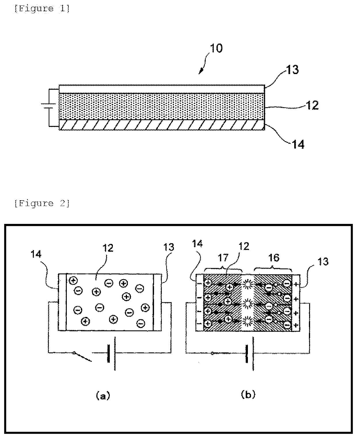
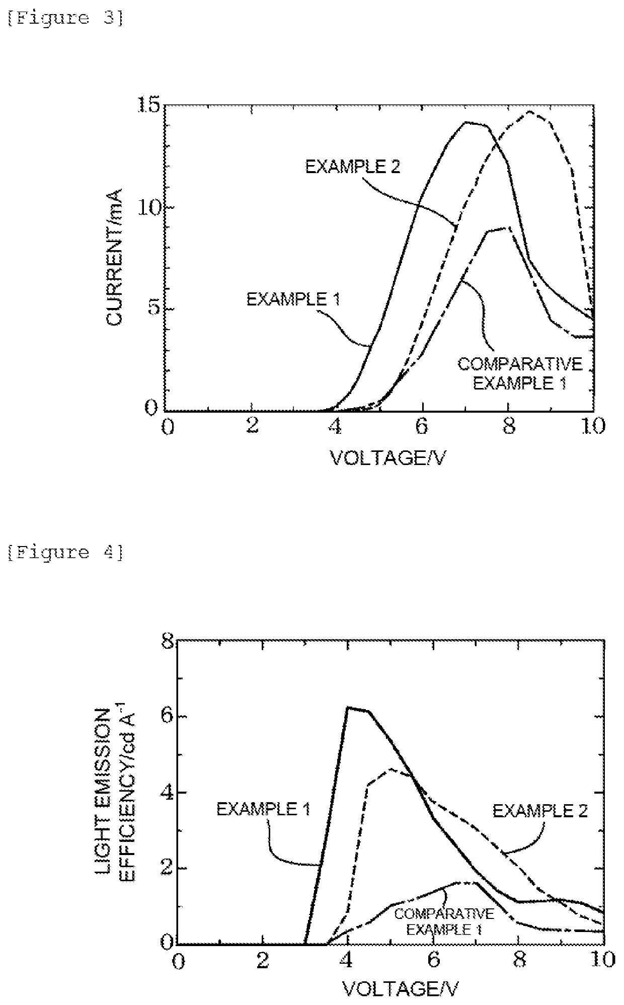
[0057]The light-emitting electrochemical cell 10 having a structure illustrated in FIG. 1 was produced. A commercially available glass substrate with an ITO film (manufactured by GEOMATEC Co., Ltd., ITO film thickness of 200 nm) was used as the first electrode 13.
[0058]The polymer material, the ionic compound, and pyrromethene 546 (1,3,5,7,8-pentamethylpyrromethene-difluoroborate complex) as the light-emitting material, which are shown in Table 1 below, were used to prepare a mixed solution thereof. Specifically, a composition for forming a light-emitting layer was prepared by mixing a monochlorobenzene solution of the polymer material (concentration: 9 g / L), a monochlorobenzene solution of the ionic compound (concentration: 9 g / L), and a monochlorobenzene solution of pyrromethene 546 (concentration: 4.5 g / L) in a mass ratio of polymer material solution:ionic compound solution:pyrromethene 546 solution=80:15:5 in an argon atmosphere in a glove box at room temperature.
[0059]Next, the...
example 2
[0061]The same operation as in Example 1 was performed except that pyrromethene 597 (1,3,5,7,8-pentamethyl-2,6-di-t-butylpyrromethene-difluoroborate complex) was used in place of pyrromethene 546 as the light-emitting material in Example 1. A monochlorobenzene solution of pyrromethene 597 was prepared at room temperature. The concentration of the monochlorobenzene solution of pyrromethene 597 was set to 9 g / L. In this way, a composition for forming a light-emitting layer was prepared, and a light-emitting electrochemical cell was produced using this composition.
example 3
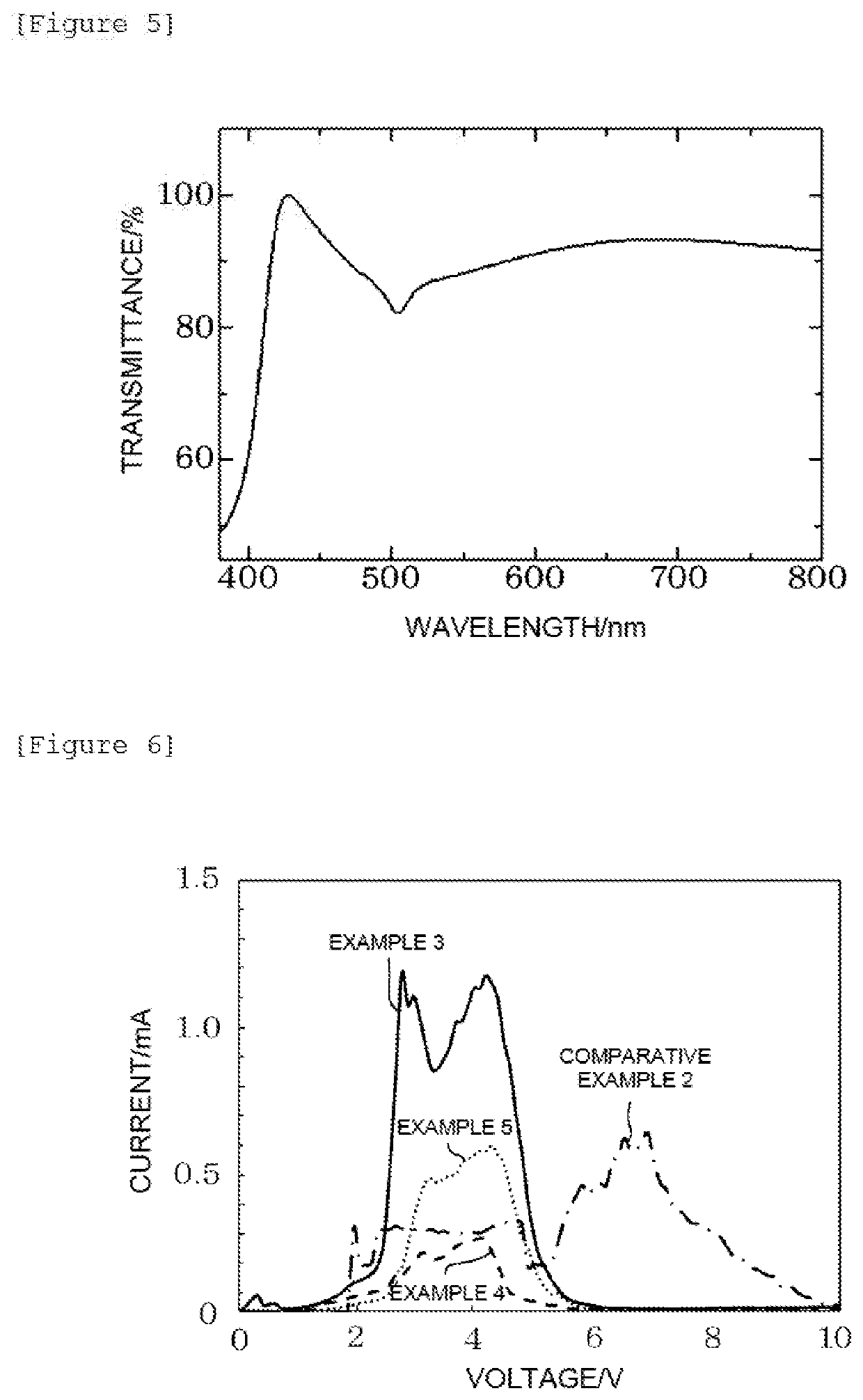
[0062]A composition for forming a light-emitting layer was prepared in the manner as described below in Example 1. The composition for forming a light-emitting layer was prepared by mixing a monochlorobenzene solution of the ionic compound (concentration: 18 g / L), a monochlorobenzene solution of pyrromethene 546 (concentration: 4.5 g / L), and a cyclohexanone solution of dibutyl phthalate (concentration: 18 g / L) as an additive with the polymer material shown in Table 1 in a mass ratio of polymer material solution:ionic compound solution:pyrromethene 546 solution:additive solution=47.5:23.75:23.75:5. In addition, a glass substrate on which the composition for forming a light-emitting layer was applied was heated to evaporate monochlorobenzene and cyclohexanone. The light-emitting electrochemical cell 10 was produced in the same manner as in Example 1, excluding those described above.
PUM
| Property | Measurement | Unit |
|---|---|---|
| Structure | aaaaa | aaaaa |
| Transparency | aaaaa | aaaaa |
Abstract
Description
Claims
Application Information
 - R&D
- Intellectual Property
- Life Sciences
- Materials
- Tech Scout
- Unparalleled Data Quality
- Higher Quality Content
- 60% Fewer Hallucinations
Browse by: Latest US Patents, China's latest patents, Technical Efficacy Thesaurus, Application Domain, Technology Topic, Popular Technical Reports.
© 2025 PatSnap. All rights reserved.Legal|Privacy policy|Modern Slavery Act Transparency Statement|Sitemap|About US| Contact US: help@patsnap.com


