
Cleaning apparatus and method for chip-stacked structure

Inactive Publication Date: 2019-11-14
GRAND PLASTIC TECH
View PDF0 Cites 0 Cited by
  • Summary
  • Abstract
  • Description
  • Claims
  • Application Information

AI Technical Summary

Benefits of technology

The present disclosure provides a cleaning apparatus and method using a moving mechanism to accurately control the position of a liquid suction device. This prevents excessive downforce on the chip stacked structure and avoids damage or leakage of gas or liquid. The flexible skirt at the bottom of the liquid suction device ensures a safe and complete cleaning process. This vertical lifting mechanism and flexible skirt make this cleaning apparatus safer and more efficient in protecting chips during the cleaning process.

Problems solved by technology

Therefore, how to remove the residues in such a tiny gap is a technical bottleneck and challenge that urgently need to be overcome.
Also, a downforce exerted by the liquid suction device at this relatively high location of the chip is also relatively large, resulting in chip damage.
Therefore, when the liquid suction device is in operation, gas and liquid drawn from the inside of the chip stacked structure are easily dissipated to the outside through the gaps between the rollers or the bristles of the brush, and cannot be completely drawn into a discharge pipe of the liquid suction device.

Method used


Image

  • Cleaning apparatus and method for chip-stacked structure
  • Cleaning apparatus and method for chip-stacked structure
  • Cleaning apparatus and method for chip-stacked structure

Examples


Embodiment Construction

[0030]The structure and the technical means adopted by the present disclosure to achieve the above and other objects can be best understood by referring to the following detailed description of the preferred embodiments and the accompanying drawings.

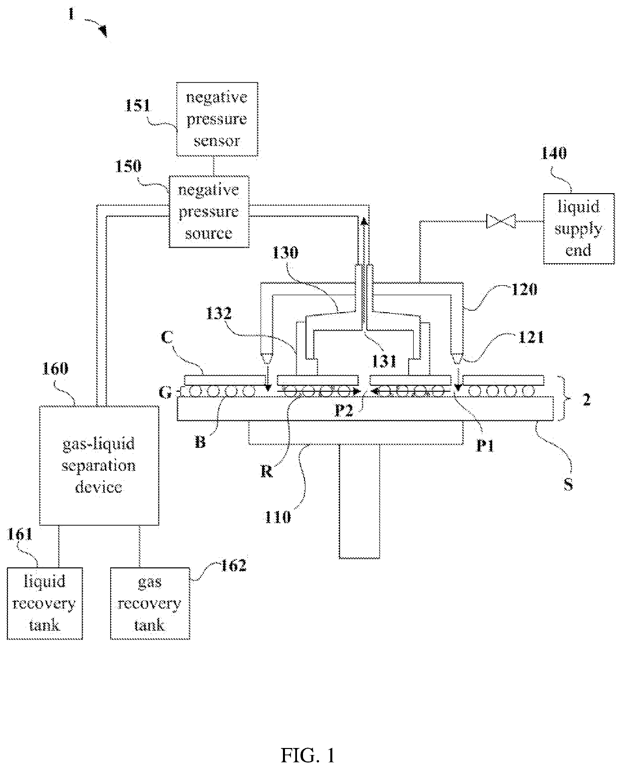
[0031]Referring to FIG. 1, which shows a schematic diagram of a cleaning apparatus according to a first preferred embodiment of the present disclosure. The cleaning apparatus 1 is used for removing residues on the chip stacked structure 2. The chip stacked structure 2 is a three-dimensional integrated circuit board that includes a substrate S and a plurality of chips C arranged in an array. A plurality of connection members B are provided between the chips C and the substrate S. The connection member B can be a solder ball that solders the substrate S and chips C or any suitable element. The connection member B is used to connect the substrate S and the chips C such that the substrate S and the chips C are separated by a gap G. The subst...


PUM


Abstract

A cleaning apparatus for removing residues from a chip stacked structure includes a platform on which the chip stacked structure is placed. A liquid supply device is for applying a cleaning liquid to the chip stacked structure to flow into a gap between chips and a substrate from a first side of the gap. A liquid suction device has a flexible skirt for engaging with the chips and is for providing a negative pressure to extract the cleaning liquid located in the gap through a second side of the gap, thereby bringing out the residues. A precise driving device is connected with the liquid suction device and has a vertical lifting mechanism for controlling the liquid suction device to move along a vertical direction, and a horizontal moving mechanism for controlling the liquid suction device to move along a horizontal direction.

Description

FIELD OF DISCLOSURE[0001]The present disclosure relates to a cleaning apparatus and method, and more particularly to a cleaning apparatus and method for removing residues from a chip stacked structure.BACKGROUND[0002]A general three-dimensional integrated circuit packaging process includes four steps: via formation, via filling, wafer thinning, and wafer bonding. A rinsing step must be performed before and after each of the four processing steps to avoid contamination of the wafer during processing thereof. Furthermore, the step of wafer bonding can be roughly divided into three types: chip to wafer (C2W), chip to chip (C2C), and wafer to wafer (W2W). However, a gap either formed between the wafers or formed between the wafer and the chip is usually 20 to 50 μm. Therefore, how to remove the residues in such a tiny gap is a technical bottleneck and challenge that urgently need to be overcome.[0003]Taiwan Patent Publication No. TW 1539515 has disclosed a cleaning method of chip stacke...

Claims


Application Information

Patent Timeline
IPC IPC(8): H01L21/67B08B3/14H01L21/02
CPCH01L21/6704B08B3/14H01L21/02057H01L21/67051H01L25/0657
Inventor HUANG, FU-YUANWU, ZONG-ENWANG, CHIH-CHENG
Owner GRAND PLASTIC TECH
Learn More