Distributed Control System for Thermal Snow Melt and Freeze Protection Systems

a technology of distribution control system and thermal snow melt protection system, which is applied in the direction of defrosting, domestic cooling apparatus, application, etc., to achieve the effect of optimizing the performance of the system

Active Publication Date: 2019-11-28
AEF ICE SYST INC
View PDF8 Cites 9 Cited by
  • Summary
  • Abstract
  • Description
  • Claims
  • Application Information

AI Technical Summary

Benefits of technology

[0008]The invention is a thermal ice mitigation system and method for surfaces and structures including heated zones, each including one or more heaters, connected to an electrical distribution system that is monitored and operated by a control system. The method and system can be designed to reduce snow and ice buildup on the surfaces or structures by either melting any incoming precipitation on contact (anti-icing) or by melting buildup at some interval (intermittent de-icing). Each surface or structure may be divided into heated sections, or zones, to allow each section, or zone, to be controlled independently. Each independent section may deliver only the required amount of thermal energy to melt the incoming precipitation (in anti-icing mode), or to melt or shed the buildup on that section (in intermittent de-icing mode). A sectioned heating system takes advantage of the fact that both heat loss to convection and the thermal energy required to melt / prevent snow and ice buildup vary, about the surface or structure. In a sectioned heating system, areas with more buildup may use more heat than areas with little or no build up, and a structure with independently controlled sections can more efficiently mitigate an entirety of the structure.
[0009]Accordingly, a control method and system of the present invention operates one or more heaters of every zone in such a way that overall energy use, and dangerous snow and ice buildup across the entirety of a structure, are minimized. One or more controllers may use temperature sensing to determine if snow is present on each heated zone. The controllers can also be set to cap the electrical output at a certain level to reduce the total system demand. In the case where total output is capped, the system can distribute power to more problematic areas first. For example, areas situated to have the greatest risk of falling snow and ice, to persons located below or thereabout, can be prioritized. Under limited power conditions, these areas can be melted first. The methods and systems of the present invention will then move to lower priority, less problematic areas. The risk of falling snow and ice is a product of the time an accretion is in place and the likelihood that the falling accretion will cause damage. Overall risk can be minimized by targeting (i.e. heating) the highest risk areas first.

Problems solved by technology

The risk of falling snow and ice is a product of the time an accretion is in place and the likelihood that the falling accretion will cause damage.

Method used


Image

  • Distributed Control System for Thermal Snow Melt and Freeze Protection Systems
  • Distributed Control System for Thermal Snow Melt and Freeze Protection Systems
  • Distributed Control System for Thermal Snow Melt and Freeze Protection Systems

Examples


Embodiment Construction

[0035]The present invention will be better understood with reference to the following description taken in combination with the drawings. For the purpose of illustration, there are shown in the drawings certain embodiments of the present invention. In the drawings, like numerals indicate like elements throughout. It should be understood, however, that the invention is not limited to the precise arrangements, dimensions, and instruments shown:

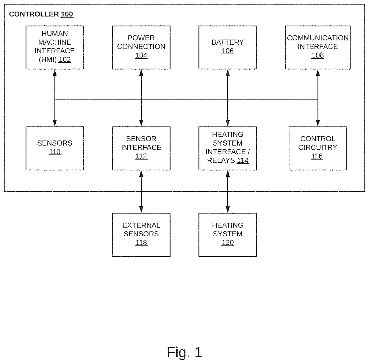
[0036]FIG. 1 illustrates an example of an intelligent, network-connected controller;

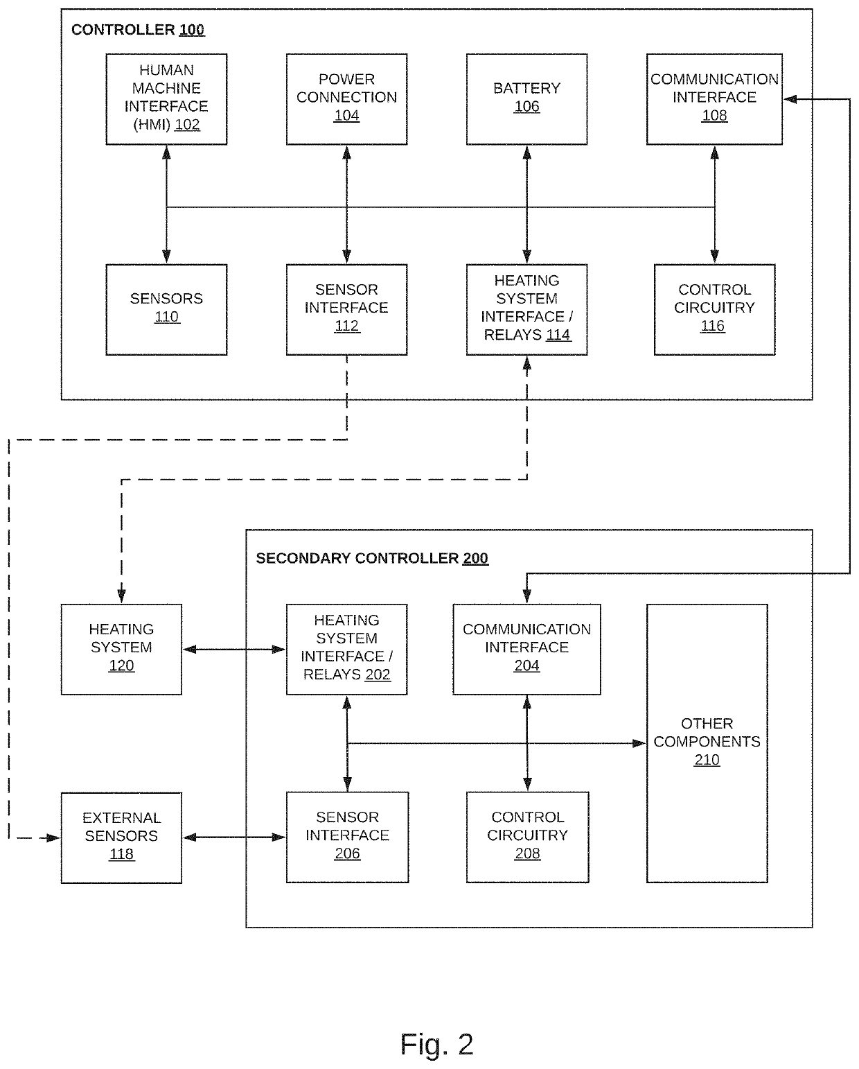
[0037]FIG. 2 illustrates an example of an intelligent, network-connected controller system consisting of a primary and secondary controller;

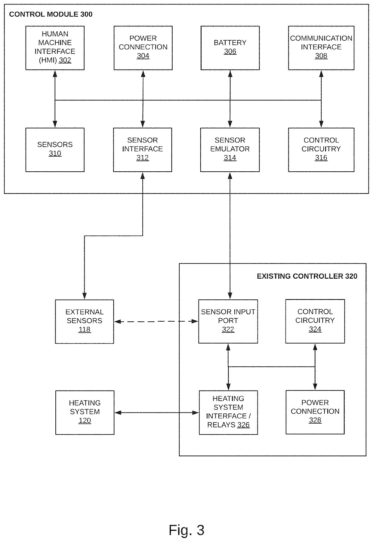
[0038]FIG. 3 illustrates an example of an intelligent, network-connected control module that may add functionality to an existing controller;

[0039]FIG. 4 illustrates an example of a smart building environment within which one or more of the devices, methods, systems, and / or services described further herein can be applied;

[00...


PUM


Abstract

A snow and ice melt system having one or more zones, each including one or more heaters, and having one or more controllers configured to use a power output of each heater and an average temperature of each zone to determine operational control of each heater to achieve a specified result. Hydronic or resistive heaters could be used. The controllers may be configured to use a system temperature response over time to determine if a phase change of the snow or ice is occurring. The phase change might indicate that snow or ice is present on a zone and is melting. Use of a first derivative of the system temperature response over time might determine a percentage of a zone covered by snow or ice. Use of a second derivative of the system temperature response over time might determine whether melting is complete.

Description

RELATED APPLICATIONS[0001]This application claims benefit of priority of: U.S. Provisional Application No. 62 / 676,350, filed May 25, 2018; and U.S. Provisional Application No. 62 / 676,362, filed May 25, 2018. Each of the above-identified related applications are incorporated herein by reference.FIELD OF THE INVENTION[0002]The present invention relates generally to thermal snow melt and freeze protection methods and systems; and more particularly to distribution control systems directed thereto, a methods and systems providing anti-icing, de-icing, and / or intermittent de-icing of surfaces and structures.BACKGROUND OF THE INVENTION[0003]Snow and ice accretes on surfaces and structures in cold climates. Such accretions can cause damage to property, cause injury, or adversely alter the dynamics of a system. For example, accretions on elevated surfaces may fall off in an uncontrolled manner resulting in a hazard to whatever lies below. Accretions on surfaces such as roads, driveways, side...

Claims


Application Information

Patent Timeline
Patent Type & Authority Applications(United States)
IPC IPC(8): F25D21/02F25D21/08F25D21/00
CPCF25D21/08F25D21/02F25B2700/11F25D21/006D07B1/147D07B5/002D07B2201/2088D07B2201/2089D07B2401/203D07B2501/203E01D19/16E01D11/04H02G7/16
Inventor BROWN, ALEXANDER F.KUSTER, TRAVIS M.
Owner AEF ICE SYST INC
Why Eureka
Try Eureka