Design Method for Civil Engineering of Reality Scenery

Inactive Publication Date: 2019-11-28
CHIANG CHUN SHENG
View PDF0 Cites 7 Cited by
  • Summary
  • Abstract
  • Description
  • Claims
  • Application Information

AI Technical Summary

Benefits of technology

[0022]Since the 3D model has been calibrated to match the absolute coordinates at the reference points on the construction site, the designer may directly retrieve data from the 3D model after being calibrated. F

Problems solved by technology

So, a design error or deviation from the real image may occur to cause disputes between the designer and his or her client.
However, the image as taken by satellite or drone just reveals a relative coordinate corresponding to the absolute coordinate of the real construction site, to thus produce an error, especially an elevation error, between the relative coordinate and the absolute coordinate.
Such an error may cause unprecise design and wrong estimation or calculation for the relevant data.
Therefore, such a conventional engineering design may cause a great error, being unable to have a precise design and also increa

Method used


Image

  • Design Method for Civil Engineering of Reality Scenery
  • Design Method for Civil Engineering of Reality Scenery
  • Design Method for Civil Engineering of Reality Scenery

Examples


Embodiment Construction

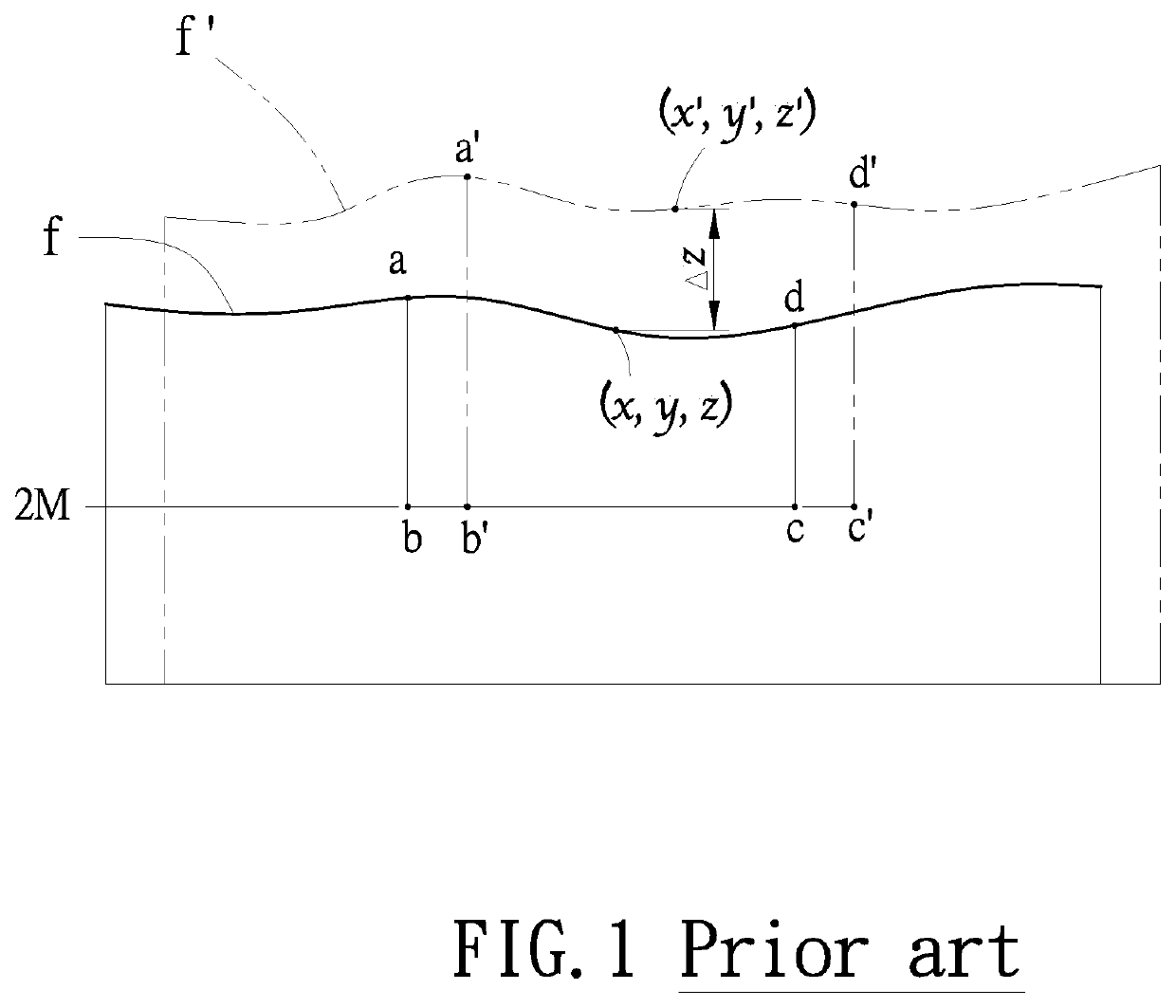
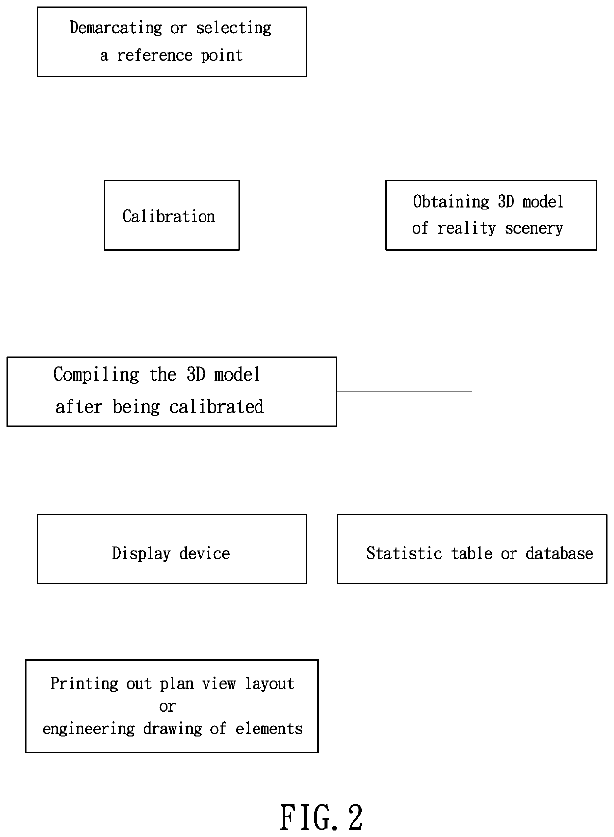
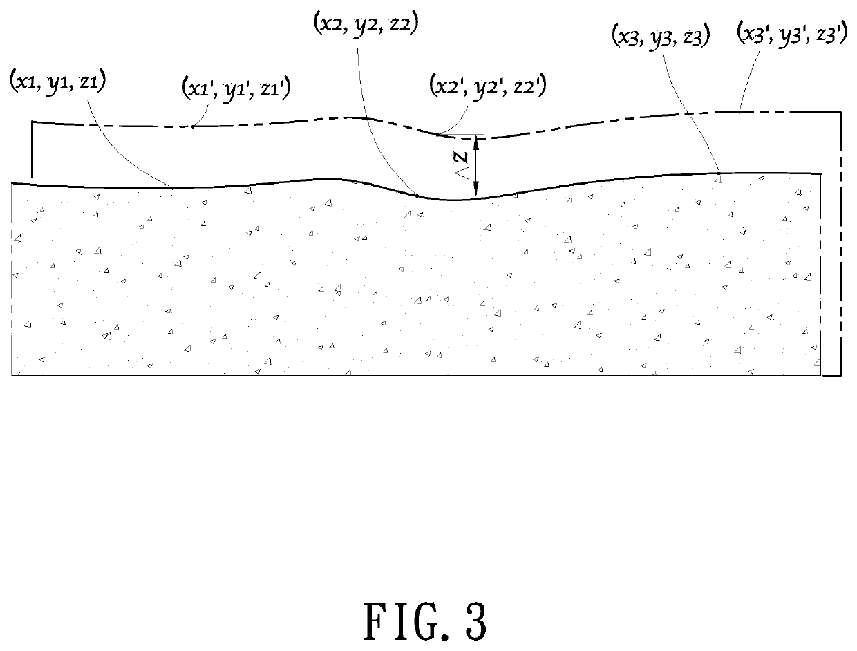
[0028]As shown in FIGS. 2-3, a design method for civil engineering of reality scenery of the present invention comprises the following steps:[0029]1. Selecting or demarcating at least a reference point at a construction site: The coordinate of the construction site is defined as an absolute coordinate. For instance, a planar coordinate includes an abscissa of X-axis and an coordinate of Y-axis. An elevation of Z-axis is added to the planar coordinate to form a three-dimensional (3D) coordinate of x, y and z. As shown in FIG. 3, three absolute coordinate sets are exemplified, namely, (x1, y1, z1), (x2, y2, z2), and (x3, y3, z3).[0030]2. Establishing a three-dimension (3D) model of a reality scenery by obtaining an image of the construction site through a camera including a digital camera based on a 3D relative coordinate of x′, y′, z′. As shown in FIG. 3, three relative coordinate sets are exemplified, namely, (x1′, y1′, z1′), (x2′, y2′, z2′), and (x3′, y3′, z3′). Such a relative coo...


PUM


Abstract

A design method for civil engineering of reality scenery includes: selecting at least a reference point at a construction site, having a coordinate of the construction site defined as an absolute coordinate, establishing a three-dimensional (3D) model of a real scene, having a coordinate of the 3D model defined as a relative coordinate relative to the absolute coordinate of the construction site, calibrating the relative coordinate corresponding to the absolute coordinate and converting the relative coordinate into the absolute coordinate, incorporating virtual 3D objects into the 3D model, synchronously displaying the projected view of the 3D model as observed through a specific viewing angle, on a display device, and setting up a statistic database for synchronously recording the virtual 3D object as input into the 3D model or objects as removed from the 3D model, and outputting the statistic data from the statistic database through an output device.

Description

BACKGROUND OF THE INVENTION[0001]In a conventional civil engineering design, a real survey should be conducted at the construction site. Then, a 3D design model may be obtained by drawings such as by AutoCAD, 3DMAX. In order to increase the scene ambiance (a feeling as attending the construction site) of the 3D model, some landscape elements or objects including street trees, mountainside, water ponds, or bridge may be added into the design features of the design model. However, such additions of landscape elements are drawn virtually (not in reality), which do not exist in the real environment. So, a design error or deviation from the real image may occur to cause disputes between the designer and his or her client.[0002]In order to increase the reality for the scenery of the real construction site, an aerial photograph by satellite or drone is provided to form a 3D model. For example, Google SketchUP is provided to obtain landforms and image data on Google Earth, which are combine...

Claims


Application Information

Patent Timeline
IPC IPC(8): G06F17/50G06T19/20G06T7/70
CPCG06T2219/2016G06T2219/2008G06T2207/30184G06T2207/10032G06T19/20G06F17/5004G06T2219/2004G06T7/70G06T2200/08G01C11/28G06F30/13B64U2101/30
Inventor CHIANG, CHUN-SHENG
Owner CHIANG CHUN SHENG
Why Eureka
Try Eureka