
Methods for manufacturing micromechanical components and method for manufacturing a mould insert component

a micromechanical and mold insert technology, applied in the field of micromechanics, can solve the problems of random shapes with non-optimal tribological properties, predetermined surface finishes, and well defined length scales of surface structures, and achieve the effect of improving the adhesion of particles

Active Publication Date: 2019-12-05
CSEM CENT SUISSE DELECTRONIQUE & DE MICROTECHNIQUE SA RECH & DEV
View PDF0 Cites 0 Cited by
  • Summary
  • Abstract
  • Description
  • Claims
  • Application Information

AI Technical Summary

Benefits of technology

The patent describes a way to make components with controlled surface cavities during manufacturing, which can improve their friction and lubrication properties without requiring further finishing. The cavities are formed by depositing particles on the sidewalls of the component, which can also help to improve adhesion. The particles can be deposited directly on the substrate, without needing to mask it. This method simplifies the manufacturing process and allows for better quality components.

Problems solved by technology

Due to the extremely small size of such components, predetermined surface finishes are required for tribological reasons.
For finishing treatments such as trowalisation or dry-wet etching without a mask, the surface structures obtained have well defined length-scales but have random shapes with non-optimal tribological properties.
Other techniques such as anodization lead to better defined surface structures but are limited to specific materials (e.g. aluminium or titanium etc.).
Laser ablation can be used to fabricate well defined surface structures at the sub-microscale but is limited in terms of throughput and feasibility when processing complex 3D microparts.
Although they allow the surface structuring of sidewalls of parts, such processes are time-consuming and are carried out on otherwise complete components, adding process steps to their manufacture and requiring handling of otherwise-finished components.

Method used


Image

  • Methods for manufacturing micromechanical components and method for manufacturing a mould insert component
  • Methods for manufacturing micromechanical components and method for manufacturing a mould insert component
  • Methods for manufacturing micromechanical components and method for manufacturing a mould insert component

Examples


Embodiment Construction

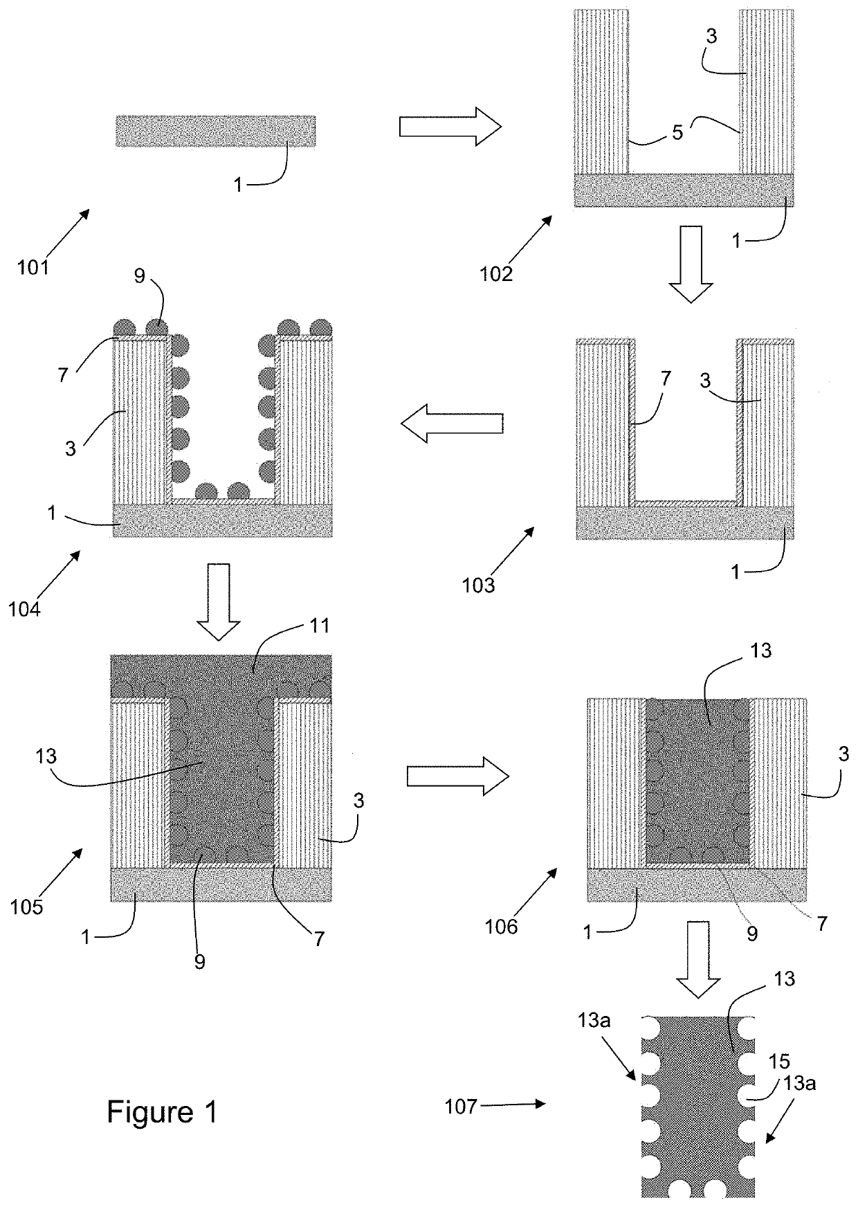
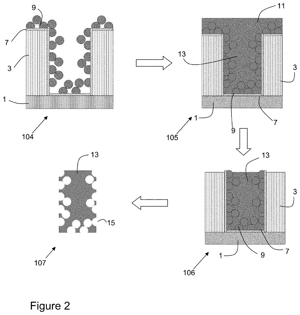
[0054]FIG. 1 illustrates a first embodiment of a method of manufacturing a micromechanical component 13 according to a method of the invention, said micromechanical component being intended to cooperate with another micromechanical component (which may or may not itself be made according to the invention) via a frictional contact, this frictional contact being either static and / or dynamic. This component 13 may be a horological or MEMS component, and may for instance be a gear wheel, a rack, a ratchet, a lever, a cam, a mainspring housing, a jumper spring, an anchor, a clutch, a sliding component, or any other component intended to interact with another via a frictional contact. This contact is typically via the sidewalls of the component 13, these sidewalls joining two faces of the component which each define a plane and which are typically parallel with each other. In other words, the sidewalls do not themselves meet in a sharp point, but rather join with a plane which is at an an...


PUM

PropertyMeasurementUnit
thicknessaaaaaaaaaa
sizeaaaaaaaaaa
sizeaaaaaaaaaa

Abstract

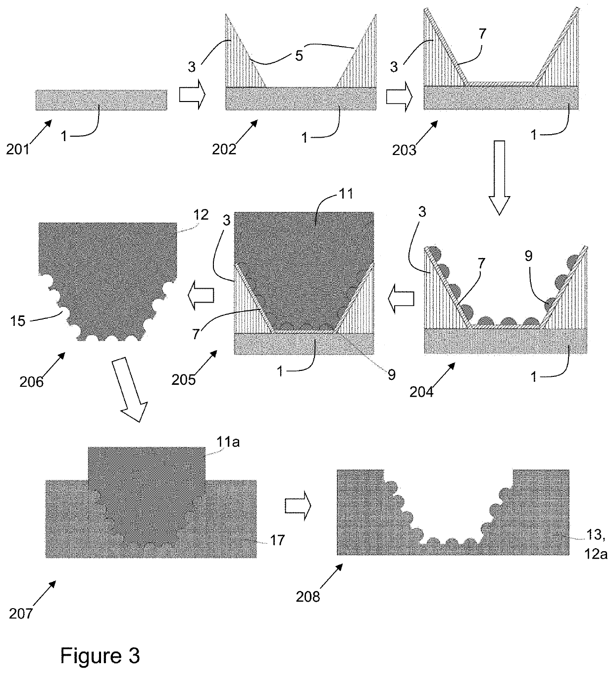
Method of manufacturing a micromechanical component intended to cooperate with another micromechanical component, the method comprising the steps of providing a substrate, forming a mould on said substrate, said mould defining sidewalls arranged to delimit said micromechanical component, providing particles on at least said sidewalls, depositing a metal in said mould so as to form said micromechanical component, and liberating said micromechanical component from said mould and removing said particles.

Description

TECHNICAL FIELD[0001]The present invention relates to the technical field of micromechanics. More particularly, it relates to methods of manufacturing micromechanical components and to a method of manufacturing a mould insert component for the manufacture of a micromechanical component.STATE OF THE ART[0002]Micromechanical components, such as horological components, MEMS components and so on, are often required to interact kinematically with each other by frictional contact.[0003]Such components, which may for instance be gear wheels, levers, cams and so on, typically have dimensions of the order of several hundred microns of thickness, and diameters or lengths ranging from several millimetres to several centimetres. Due to the extremely small size of such components, predetermined surface finishes are required for tribological reasons. The typical approach for such finishing is to first manufacture the components, and then subject them to a surface treatment such as polishing, roug...

Claims


Application Information

Patent Timeline
Patent Type & Authority Applications(United States)
IPC IPC(8): B81C99/00
CPCB81B2201/035B81C99/0085B81C99/009B81B2201/036B81B5/00B82Y40/00B81C1/00103B81C1/00484B81C2201/034
Inventor BLONDIAUX, NICOLASPUGIN, RAPHAËL
Owner CSEM CENT SUISSE DELECTRONIQUE & DE MICROTECHNIQUE SA RECH & DEV
Learn More