
Light guide plate, thin backlight module and luminous keyboard thereof

a backlight module and light guide plate technology, applied in the field of backlight modules, can solve the problems of not being able to reduce the total thickness of the keyboard to the expected thickness, the luminous cost of each key of the keyboard is more complex and expensive, and the total thickness cannot be reduced to the desired value. the effect of reducing the total thickness and reducing the cost of the produ

Active Publication Date: 2019-12-05
GLOBAL LIGHTING TECHNOLOGIES INC
View PDF4 Cites 0 Cited by
  • Summary
  • Abstract
  • Description
  • Claims
  • Application Information

AI Technical Summary

Benefits of technology

The present invention relates to a thinner and lighter keyboard design with improved luminous effect. The invention uses a light guide plate with bumps and microstructure patterns to connect the press keys, reducing the need for a separate metal base and simplifying assembly. A thin backlight module is included for providing light, and a diffusion type reflector body with mounting holes and a light shielding layer is used to improve the luminous effect. Overall, the invention provides a thinner, easier to assemble, and more pleasant luminous keyboard.

Problems solved by technology

By the method above, the assembling is more convenient, but the thickness of a relatively large position of the press key structure is occupied by the base, so that even the light guide plate is omitted, the total thickness of the keyboard still cannot be reduced to the expected thickness.
Therefore, related manufacturers continued to make improvement in another direction, and U.S. Pat. No. 9,449,772 discloses a luminous keyboard with the conventional structure and uses a butterfly-type key switch rather than the traditional scissor-type key switch to achieve the effect of shortening the stroke of the press key and the butterfly-type key switch structure reduces the total thickness, but the structure requires a support structure (such as the base described above) to fix the butterfly-type key switch, and further worse that each press key is installed with a corresponding light guide component and a light source, so that more complex and cost are required for each press key of the keyboard to have the luminous effect.
Although U.S. Pat. No. 8,097,822 filed by the applicant can reduce the total thickness by the method of omitting the light guide plate structure, yet the total thickness still cannot be reduced to a desired value due to the limitation of the base.
Furthermore, the light output performance is affected significantly without the light guide plate structure.
Although U.S. Pat. No. 9,449,772 adopts the butterfly-type switch structure to reduce the thickness, each press key needs to have a light guide component and a light source, and thus incurring a higher cost of the product and requiring to assemble the press keys one by one in an assembling operation, and wasting much time and lowering the yield rate.
The microstructure patterns destruct the total reflection of the light and thus output the light at the press button installation area.

Method used


Image

  • Light guide plate, thin backlight module and luminous keyboard thereof
  • Light guide plate, thin backlight module and luminous keyboard thereof
  • Light guide plate, thin backlight module and luminous keyboard thereof

Examples


Embodiment Construction

[0033]Reference will now be made in detail to the present embodiments of the disclosure, examples of which are illustrated in the accompanying drawings. Wherever possible, the same reference numbers are used in the drawings and the description to refer to the same or like parts.

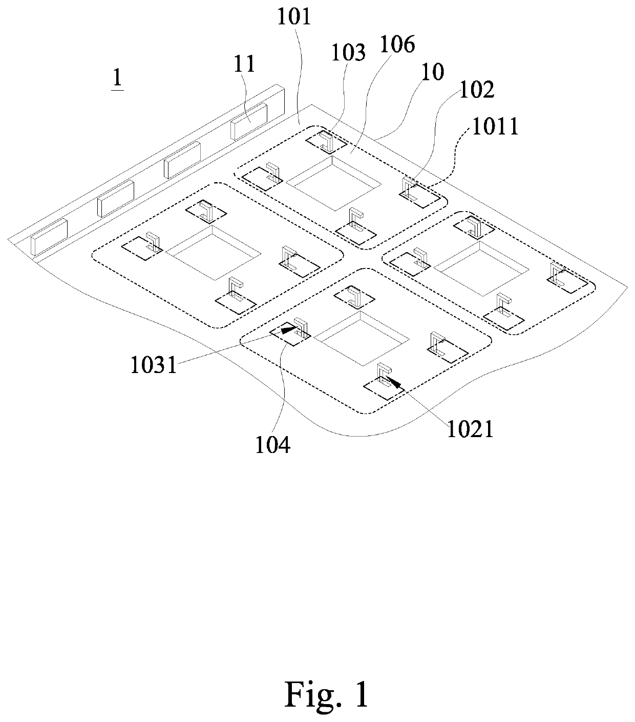
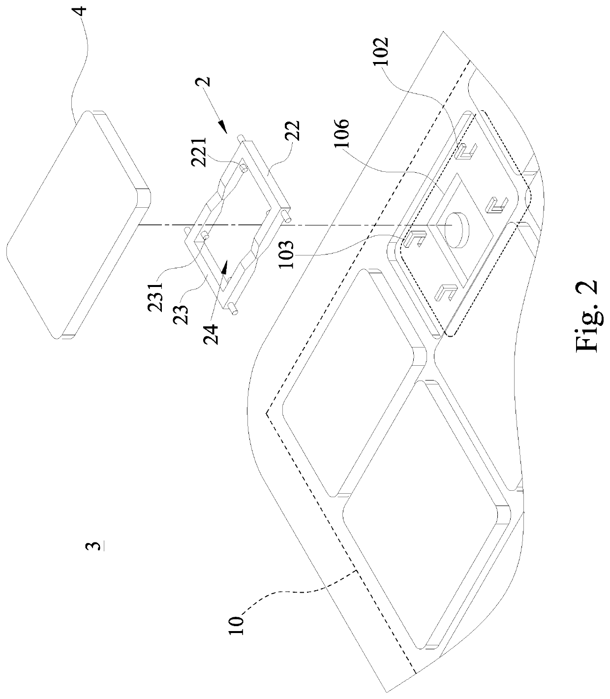
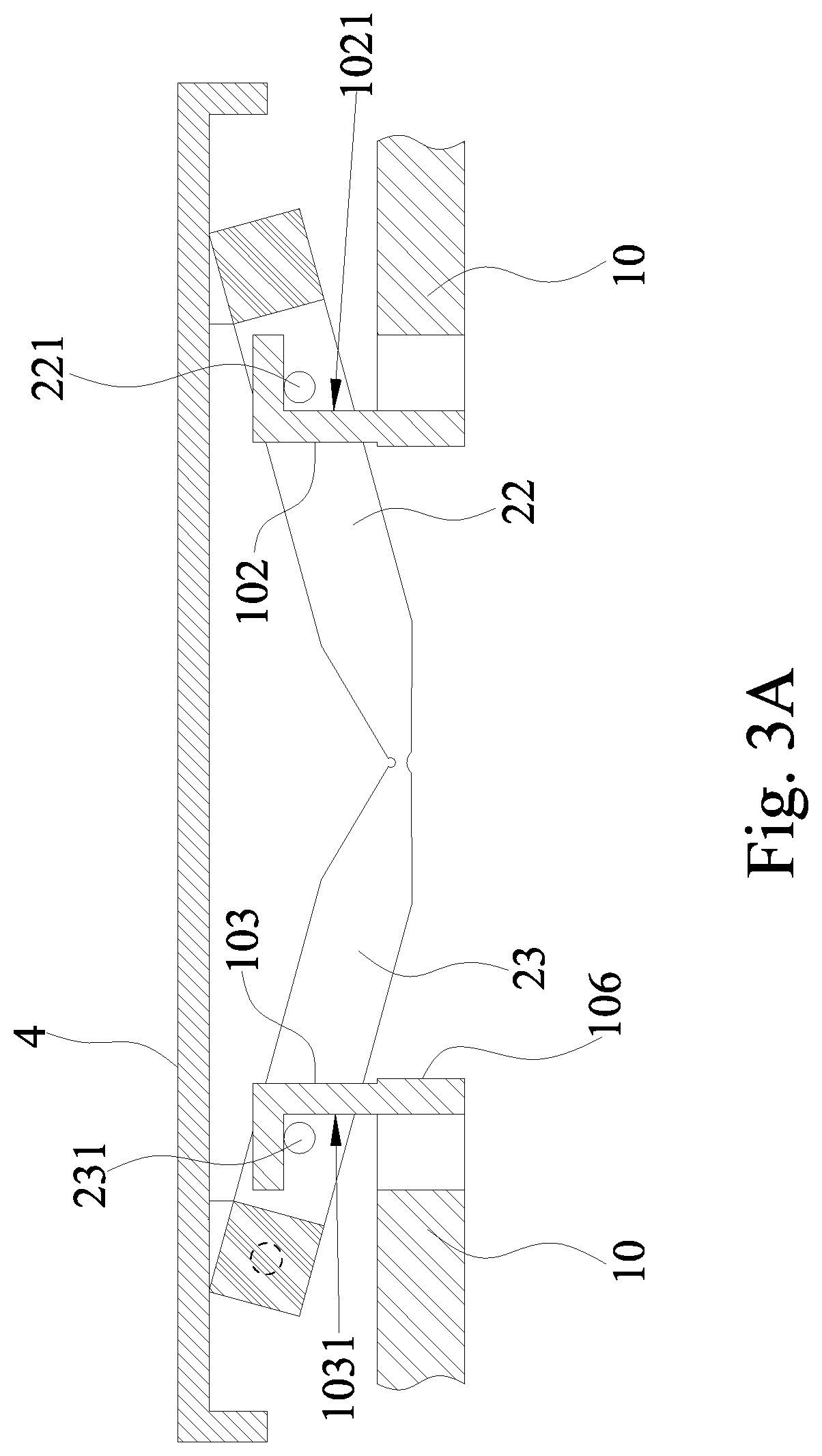
[0034]With reference to FIGS. 1-3B for a partial schematic view of a thin backlight module, a partial exploded view of a thin luminous keyboard, and cross-sectional views of assembling a thin luminous keyboard in accordance with a first implementation mode of one embodiment of the present disclosure respectively, the present disclosure discloses a thin backlight module 1 and a thin luminous keyboard 3. The thin luminous keyboard 3 comprises a thin backlight module 1, a plurality of press key structures 2, a plurality of keycaps 4 and a bottom plate 5, and the thin backlight module 1 is operated together with the press key structure 2 and applied in the thin luminous keyboard 1. The thin backlight module 1 com...


PUM


Abstract

A light guide plate provided for a luminous keyboard is disclosed. The light guide plate includes a main body, a first bump pair, a second bump pair, and many microstructure patterns. The main body has a light output surface and many press button installation areas defined thereon, each of the press button installation areas is arranged to fix a press key structure. The first bump pair and the second bump pair are integrally and seamlessly protruded from the main body. Each of the first bump pair has a first recess, and each of the second bump pair has a second recess. The first recess and the second recess are configured opposite to each other, and provided for assembling the press key structure. The microstructure patterns are formed next to the first and second bump pairs to abstract light by destructing the total reflection in the main body.

Description

CROSS-REFERENCE TO RELATED APPLICATION[0001]This application claims the priority benefit of Taiwan application serial no. 107118331, filed on May 29, 2018. The entirety of the above-mentioned patent application is hereby incorporated by reference herein and made a part of this specification.BACKGROUNDTechnical Field[0002]The present disclosure generally relates to a backlight module. More particularly, the present disclosure relates to a light guide plate applied in a luminous keyboard.Description of Related Art[0003]As the light supply technology develops, various electronic products with a luminous effect are introduced to provide users a better using experience. For example, a keyboard being a main input device of desktop or notebook computers is a popular luminous electronic product. The early keyboard did not have the luminous effect, and later related manufacturers used a light supply structure as a light source and light up each press key during an operation, so as to achieve...

Claims


Application Information

Patent Timeline
Patent Type & Authority Applications(United States)
IPC IPC(8): G06F3/02F21V8/00
CPCG02B6/0051G02B6/0035G06F3/0202G02B6/0041G02B6/006
Inventor WU, FAN-WEIHSU, CHIN-HUNG
Owner GLOBAL LIGHTING TECHNOLOGIES INC
Learn More