
Lateral-flow microfluidic chip and flow velocity control method thereof

a microfluidic chip and flow velocity technology, applied in the field of lateral flow microfluidic chip and flow velocity control method, can solve the problems of relative proportion of working age population, difficult to establish medical insurance coverage, and difficulty in determining the degree of working ag

Inactive Publication Date: 2019-12-12
THE IND & ACADEMIC COOP IN CHUNGNAM NAT UNIV (IAC)
View PDF2 Cites 0 Cited by
  • Summary
  • Abstract
  • Description
  • Claims
  • Application Information

AI Technical Summary

Benefits of technology

The present patent describes a method for manufacturing a microfluidic chip with a liquid reservoir that accelerates the flow velocity of a fluid by increasing the vapor pressure around the channel. By having a wider liquid reservoir than the channel, the chip effectively exhibits acceleration without increasing its size or decreasing its efficiency. The method allows for easy and economical mass-production of the microfluidic chip. The patent also mentions that the chip can be manufactured with a separate process or physical operation by designing a channel to have a liquid reservoir. Additionally, the patent suggests that the vapor pressure can be supplied by an external device such as a humidifier or a humidifying chamber. Overall, the patent provides a simple and efficient way to manufacture and mass-produce microfluidic chips with improved flow kinetics.

Problems solved by technology

With the advent of aging society, the relative proportion of working age population has been decreasing, and with an increase of elderly population who have a higher incidence of diseases, medical diagnosis costs have become a serious problem.
Even developing countries where medical insurance coverage is not well-established are experiencing difficulties due to costs for diagnosing diseases of individuals.
The test method has advantages in that detection is intuitive, simple, and takes short time, but has a disadvantage in that sensitivity of diagnosis is low.
However, an erroneous result may be derived when unskilled users fail to inject samples according to predetermined positions, orders, and time intervals, and even skilled users have to endure inconvenience of having to perform the task several times. Accordingly, to obtain a reproducible result while allowing convenient use by unskilled general users, controlling flow velocity of a fluid in a specific channel is essential to allow sequential reactions even with one task.
In addition, the physical methods include cases in which a magnetic valve is used, or a melting bridge manufactured by pullulan or sugar is placed between channels so that, after a fluid flows for a predetermined amount of time, the bridge melts and disappears and thus delays the fluid flow.
On the contrary, the method in which a channel is treated with an additional substance at every specific position or a valve is installed not only requires a separate process but also requires that the additional substance or the valve be aligned at accurate positions of the corresponding channel such that a manufacturing cost of the paper chips increases.
However, since a flow velocity adjustment in a specific channel for sequential reactions is performed by delaying the flow velocity in all of the above-described methods of the related art, the methods have a problem in that a time taken for analysis is prolonged.

Method used


Image

  • Lateral-flow microfluidic chip and flow velocity control method thereof
  • Lateral-flow microfluidic chip and flow velocity control method thereof
  • Lateral-flow microfluidic chip and flow velocity control method thereof

Examples


example 1

eleration of Fluid in Paper Chip to which Liquid Reservoir is Adopted

[0037]1) Check Influence of Liquid Reservoir on Flow Velocity

[0038]It was predicted that a flow velocity would increase in a paper chip when a liquid reservoir is placed at both sides of a channel and a vapor pressure is selectively increased in the channel, and this was confirmed through an experiment.

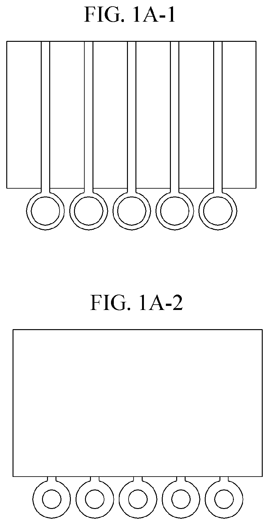
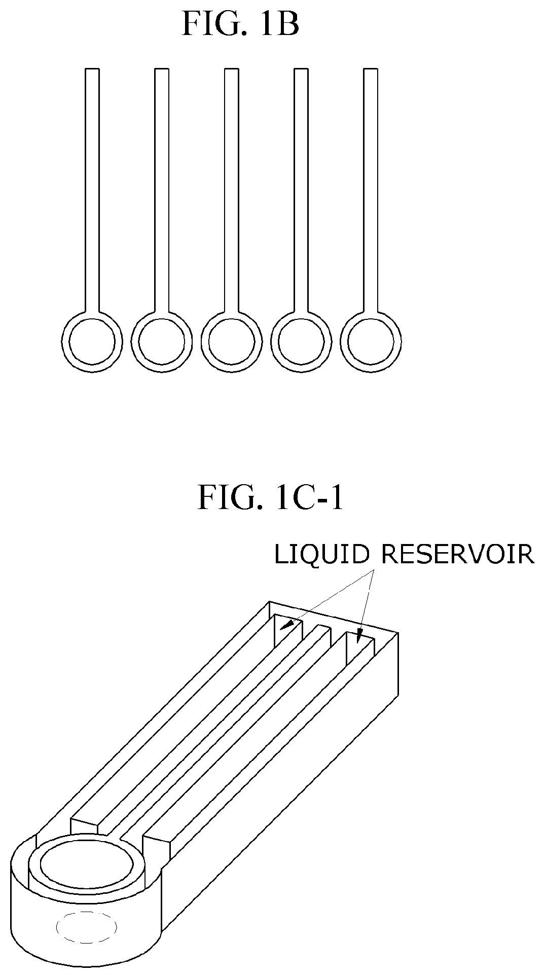
[0039]For the confirmation, on a sheet of Whatman 3MM chromatography paper, a circular sample injecting portion having a diameter (inner diameter) of 12 mm and a shape of a channel which is connected to the injecting portion and has a width of 2 mm and length of 60.5 mm were designed using Adobe Illustrator CS6 program. A liquid reservoir having a width of 12.5 mm and a length of 57.2 mm was designed to be disposed at both sides of the channel at a distance of 1.5 mm from the channel. For the comparison of flow velocities, a paper chip in which the liquid reservoir is not formed was also designed. On a bottom end of ...

example 2

eleration of Fluid in Paper Chip in which Sample Pad is Utilized as Liquid Reservoir

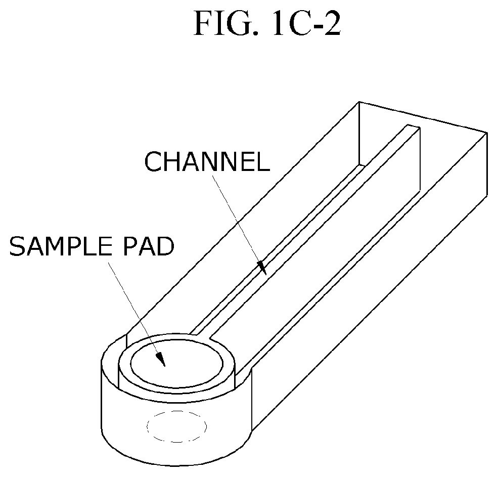
[0046]To eliminate an inconvenience of having to separately pour a liquid into a separately-formed liquid reservoir as in Example 1, usefulness of design of a channel of a paper chip in which a sample pad itself may be used as a liquid reservoir was confirmed. FIG. 5A is a conceptual diagram of a channel of the paper chip in which a sample pad serves as a liquid reservoir, and FIG. 5B show designs of a front surface of a sheet of paper using Adobe Illustrator CS6 program. The method of manufacturing the paper chip is the same as that in Example 1, and numerical values used in the design are indicated in Table 1.

TABLE 1ElementSizeChannel width2 mmGap1 mmSample pad13 mm*26 mm

[0047]To facilitate observation of the flow of the fluid in the completed paper chip, 2 μl of magenta ink was adsorbed onto a corner of left path, 2 μl of cyan ink was adsorbed onto a corner of right path, and then the adsorbed ink...


PUM

PropertyMeasurementUnit
lengthaaaaaaaaaa
widthaaaaaaaaaa
inner diameteraaaaaaaaaa

Abstract

The present disclosure relates to a method of accelerating a flow velocity in a lateral-flow microfluidic chip in which an analysis time is not delayed while sequential reactions are possible in the lateral-flow microfluidic chip by accelerating a flow velocity in at least a section of a channel, it is easy to manufacture the microfluidic chip for applying the method, and it is possible to mass-produce the microfluidic chip, and more particularly, by increasing a vapor pressure around a specific channel, a flow velocity of a fluid in the corresponding channel is accelerated.

Description

CROSS-REFERENCE TO RELATED APPLICATION[0001]This application claims priority to and the benefit of Korean Patent Application No. 10-2018-0066917, filed on Jun. 11, 2018, the disclosure of which is incorporated herein by reference in its entirety.BACKGROUND1. Field of the Invention[0002]The present disclosure relates to a lateral-flow microfluidic chip and a method of controlling a flow velocity of a channel in the lateral-flow microfluidic chip.2. Discussion of Related Art[0003]With the advent of aging society, the relative proportion of working age population has been decreasing, and with an increase of elderly population who have a higher incidence of diseases, medical diagnosis costs have become a serious problem. Even developing countries where medical insurance coverage is not well-established are experiencing difficulties due to costs for diagnosing diseases of individuals. In order to solve such problems, low-cost diagnostic equipment capable of diagnosing a disease with a lo...

Claims


Application Information

Patent Timeline
Patent Type & Authority Applications(United States)
IPC IPC(8): B01L3/00G01N33/53
CPCB01L2300/126B01L3/50273G01N33/5302B01L2200/06B01L2400/0403G01N33/558G01N33/54366B01L3/5023B01L2200/0694B01L2200/142B01L2300/0825B01L2300/0858B01L2400/0406B01L2400/084B01L2300/10B01L2400/0487B01L2300/0861B01L2300/088
Inventor LEE, CHANG SOOJEONG, SEONG GEUNLEE, JIN HYEONSONG, NA MIYANG, CHANG HWAN
Owner THE IND & ACADEMIC COOP IN CHUNGNAM NAT UNIV (IAC)
Learn More