Automatic analyzer for the detection of chemical elements in organic compounds

Inactive Publication Date: 2019-12-19
ECOENERGETICS
0 Cites 0 Cited by

AI-Extracted Technical Summary

Problems solved by technology

Moreover, with this type of combustion, pyrolysis residues in the form of powders can be formed, and in any case, mass losses with respect to the quantitative analysis can occur.
Especially in this type of combustion, large amounts of O2 are required, which must be pure up to the fifth decimal place, which causes a considerably h...

Method used

[0046]Therefore, the combustion is also quantitative and is carried out in a heterogeneous phase by the catalys...

Abstract

The invention relates to an automatic analyzer for organic elemental analysis, said analyzer comprising:
    • lines for gaseous fluids,
    • sample holders to be analyzed,
    • a catalytic combustion reactor,
    • a water adsorber,
    • an organic compounds detector, and a logical unit for detection data processing, wherein the analyzer further comprises an automatic oxygen meter and the oxygen supply to the catalytic combustion reactor is managed by the data processing unit as a function of the stoichiometric requirement calculation and of the operating time of the oxygen meter.

Application Domain

Dental implantsChemical analysis using combustion +4

Technology Topic

ChemistryOxygen meters +9

Image

  • Automatic analyzer for the detection of chemical elements in organic compounds
  • Automatic analyzer for the detection of chemical elements in organic compounds
  • Automatic analyzer for the detection of chemical elements in organic compounds

Examples

  • Experimental program(1)

Example

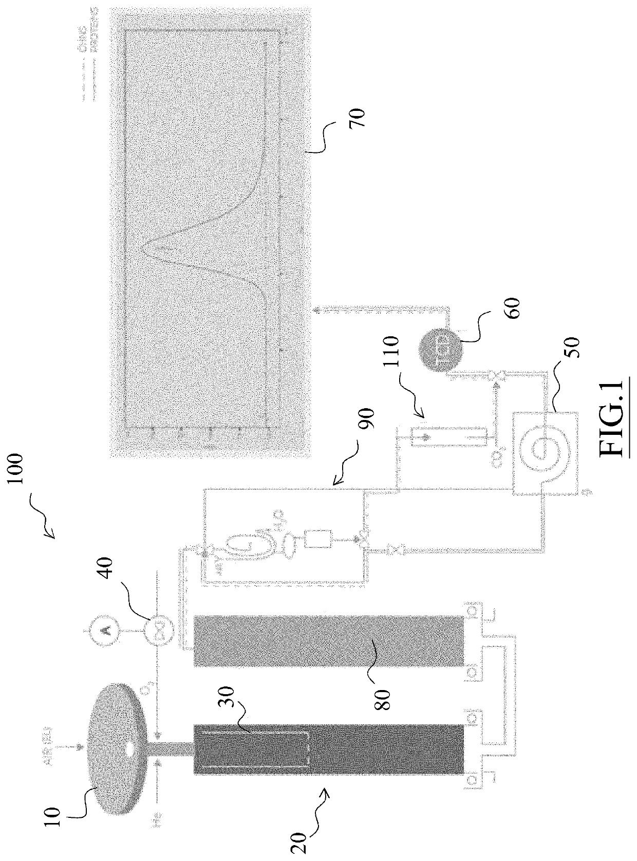
[0023]In particular, FIG. 1 shows a flow chart of a first embodiment of the analyzer of the invention, indicated as a whole by reference numeral 100.
[0024]The analyzer 100 is equipped with an automatic sampler 10, preferably a 120 position-sampler, consisting of three overlapping carousels each comprising 40 positions.
[0025]The sampler 10 is driven by a pneumatic device which, while allowing a sample to fall into the combustion reactor, simultaneously loads the next sample on a piston-driven slide within the sampler. Through the sampler, oxygen and helium are also introduced into the system.
[0026]The sampler 10 is provided with a “purging” zone to flush any air residues (i.e. N2) with a He flow.
[0027]The sampler 10 feeds samples weighed and contained in Tin or Silver capsules to an oxidation reactor 20 which has a first stage consisting of a combustion chamber and an ash accumulation zone, also including a quartz pipe indicated with 30.
[0028]As better shown in FIG. 2, the oxidation reactor 20 can include a second stage 35 containing a suitable catalytic bed where the fast oxidation reaction at high temperature occurs, and a third stage 37 for a finishing oxidation reaction.
[0029]The catalysts used for the first and second stage catalytic beds are generally those already known and routinely used in the heterogeneous gas phase oxidation reactions, respectively fast and slow.
[0030]The oxidation reactor 20 is capable of bringing a minimum number of samples equal to 1000 to full oxidation before needing to replace the quartz pipe.
[0031]The catalysts consist of special mixed oxide pins supported by two layers having different surfaces stabilizing at 1000° C. and 750° C.
[0032]Downstream of the oxidation reactor 20, a reduction reactor 80 containing reduced copper and copper oxide for the reduction of NOX to nitrogen is provided, allowing to retain both the excess oxygen and the impurities consisting of S and halogens. A catalytic copper oxide bed is used for the oxidation of traces of CO to CO2.
[0033]Downstream of the reactors, a water extraction system 90 is provided, also referred to as a water absorber, comprising an outward moisture exchanger consisting of a pipe lapped by counterflow dry gases conveyed by all the emissions leaving the instrument.
[0034]A microfilter of a substance capable of adsorbing any non-evaporated water traces is provided and located at the outlet of the water absorber which is preferably made of magnesium perchlorate.
[0035]Further downstream of the water extraction system 90, a CO2 adsorption device 110 is provided, which is a microadsorber consisting of one, two or three reactors contained in a Peltier principle-based device, applied to electrically active ceramic walls and containing very active zeolites. The CO2 contained in the fumes of each analysis is adsorbed until the zeolite is saturated. The fumes then pass to a second degassing furnace and the first adsorber is regenerated at high temperature to be ready for subsequent analysis.
[0036]Molecular sieves of various sizes (from about 15 to 40 grams) are used, which do not contribute to increase the pressure drop in the process.
[0037]According to the present invention, a device to ensure the flow stability is further provided, comprising an automatic oxygen meter 40 adapted to avoid pressure variations in the circuit, especially during combustion.
[0038]As also disclosed below, the automatic oxygen meter 40 is controlled by a data processing unit 70 and the oxygen supply to the catalytic combustion reactor is managed by the data processing unit 70 as a function of the stoichiometric requirement calculation and opening time of the oxygen meter 40.
[0039]The gas leaving the water extraction system 90 and the CO2 adsorption device 110 is sent to the actual analyzer consisting of a gas chromatographic column 50 (or in a variant of the invention by a mass spectrometer) and a thermoconductivity detector TCD 60 (or alternatively HWD—hot wire detection).
[0040]The TCD detector is preferably an absolute electrical conductivity detector, which in the present version does not require a reference gas flow but is based on the energy developed by a filament kept at a constant temperature since lapped by a constant flow rate gas.
[0041]Finally, the analyzer 100 includes a logical unit 70 for data processing.
[0042]The operation of the analyzer 100 may be described as follows.
[0043]An algorithm determines the amount of oxygen to be used based on the weight and nature of the sample to be analyzed and placed in a capsule inside the sampler 10.
[0044]A valve V6 is activated for the time required to obtain the calculated amount of oxygen in volume.
[0045]One of the advantages of using the aforementioned algorithm and the oxygen valve as a function of time is that negligible load losses are thus obtained during combustion even in the case of large samples.
[0046]Therefore, the combustion is also quantitative and is carried out in a heterogeneous phase by the catalysts dedicated thereto and requires a minimum amount of comburent (which also reduces the consumption of copper).
[0047]The separation of the elements generated by the combustion, in particular N2, CO2, H2O, SO2, is obtained by means of the gas chromatograph column 50 and has masses of samples from 5 μg up to 50 mg of the organic matter.
[0048]In the case of food analysis, the sample mass can reach up to 750 mg, bypassing the gas chromatograph column and using dedicated systems for the extraction of CO2 and H2O from the fumes.
[0049]FIG. 2 depicts a flow chart of an alternative embodiment of the analyzer, indicated as a whole by reference numeral 200, particularly suitable for the analysis of proteins.
[0050]In FIG. 2 the stages of the oxidation reactor 20 are better seen, i.e. the second stage 35 containing a suitable catalytic bed where the fast oxidation reaction at high temperature occurs and the third stage 37 operating at lower temperatures for a slower oxidation reaction.
[0051]The analyzer 200 in FIG. 2 does not include a gas chromatographic column.
[0052]FIG. 3 shows a further simplified embodiment of the analyzer of the invention, indicated as a whole by reference numeral 300.
[0053]This embodiment is a simplified version of the analyzer 100 described above.
[0054]FIG. 4 shows a further simplified embodiment of the analyzer of the invention, indicated as a whole by reference numeral 400.
[0055]This embodiment is a further simplified version of the analyzer 100 described above where, moreover, the reduction reactor 80 is not provided.
[0056]Due to its configuration and low cost, the analyzer 400 is suitable, for example but not exclusively, for developing countries.
[0057]Finally, FIG. 5 shows a further simplified embodiment of the analyzer of the invention, indicated as a whole by reference numeral 500.
[0058]This configuration is similar to that of the previously mentioned analyzer 400 but differs therefrom by the presence in addition to or in place of the thermal conductivity detector 60 (TCD) of a mass spectrometer 75.
[0059]Modifications or improvements may be obviously made to the invention as described, all dictated by contingent or particular need, without thus departing from the scope of the invention as claimed below.

PUM

no PUM

Description & Claims & Application Information

We can also present the details of the Description, Claims and Application information to help users get a comprehensive understanding of the technical details of the patent, such as background art, summary of invention, brief description of drawings, description of embodiments, and other original content. On the other hand, users can also determine the specific scope of protection of the technology through the list of claims; as well as understand the changes in the life cycle of the technology with the presentation of the patent timeline. Login to view more.
Why Eureka
Try Eureka