Apparatus and method for cell kill confirmation

a technology of optical signal and apparatus, applied in the direction of fluorescence/phosphorescence, instruments, optical elements, etc., can solve the problems of inability to accurately confirm the presence of sexed cells, laborious manual kill count, and inability to obtain sex, so as to achieve the effect of destroying or reducing the manual examination of cells, and ensuring the purity of the produ

Active Publication Date: 2019-12-19
ABS GLOBAL
View PDF0 Cites 6 Cited by
  • Summary
  • Abstract
  • Description
  • Claims
  • Application Information

AI Technical Summary

Benefits of technology

[0012]Therefore, it is a primary object, feature, or advantage of the invention to improve on or overcome the deficiencies in the art.
[0013]It is another object, feature, or advantage of the invention to provide a sexed semen apparatus which produces a consistently higher purity product.
[0014]It is another object, feature, or advantage of the invention to provide a sexed semen apparatus which verifies kill laser alignment is consistent throughout a run.
[0015]It is another object, feature, or advantage of the invention to provide a sexed semen apparatus which overcomes the drawbacks of an open loop system, such as kill beam alignment which drifts over time during long runtimes and bull changes.
[0016]It is still yet a further object, feature, or advantage of the invention to destroy or reduce manual examination of cells under a microscope during alignment by automating the confirmation process.
[0017]It is still yet a further object, feature, or advantage of the invention to provide a sexed semen apparatus wherein the detection and kill laser use the same wavelength and allow for gender detection and kill confirmation using only one dye.

Problems solved by technology

The kill laser strikes and destroys the undesired population of sexed cells on an individual basis through an abrupt energy pulse which disrupts the membrane of the cells, thereby causing the sexed cells to become infertile.
The manual kill count is labor intensive and requires additional consumables and lab space.

Method used


Image

  • Apparatus and method for cell kill confirmation
  • Apparatus and method for cell kill confirmation
  • Apparatus and method for cell kill confirmation

Examples


Embodiment Construction

[0079]The following definitions and introductory matters are provided to facilitate an understanding of the present invention.

[0080]The singular terms “a,”“an,” and “the” include plural referents unless context clearly indicates otherwise. Similarly, the word “or” is intended to include “and” unless the context clearly indicate otherwise. The word “or” means any one member of a particular list and also includes any combination of members of that list.

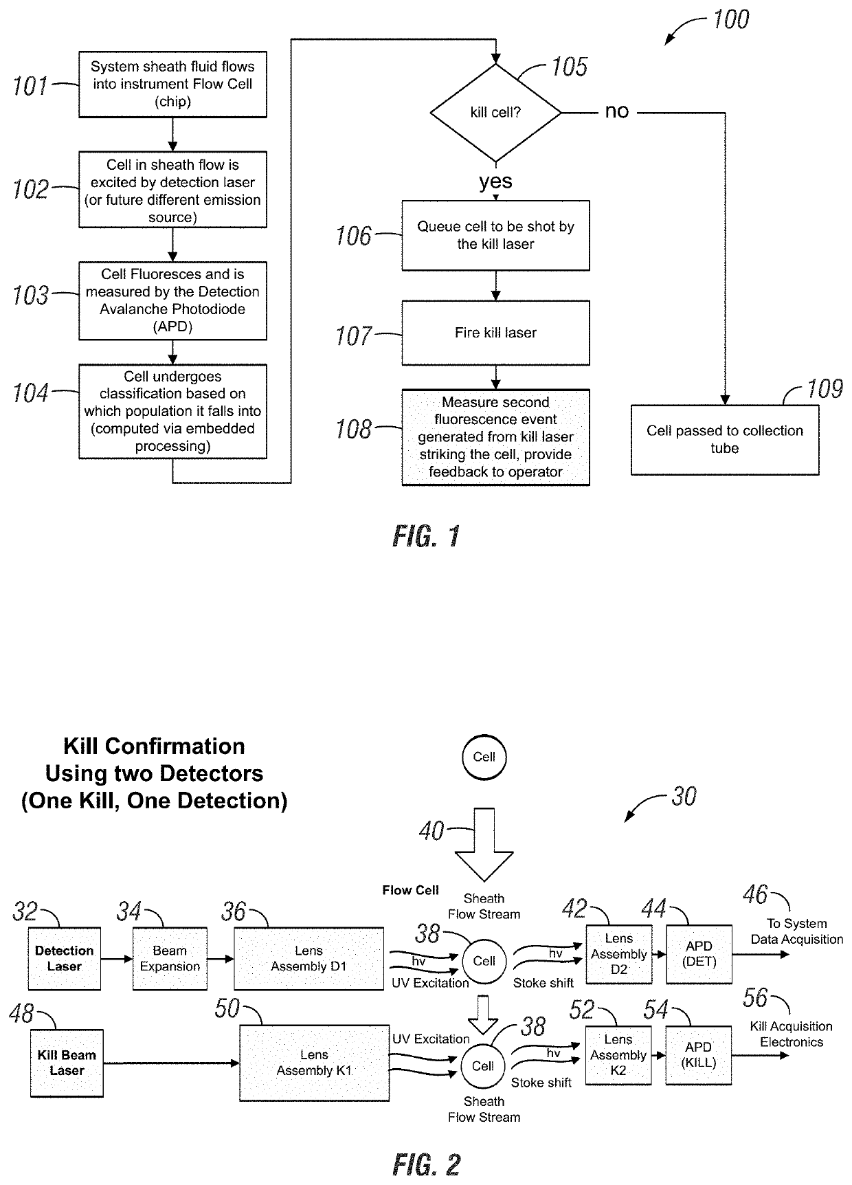
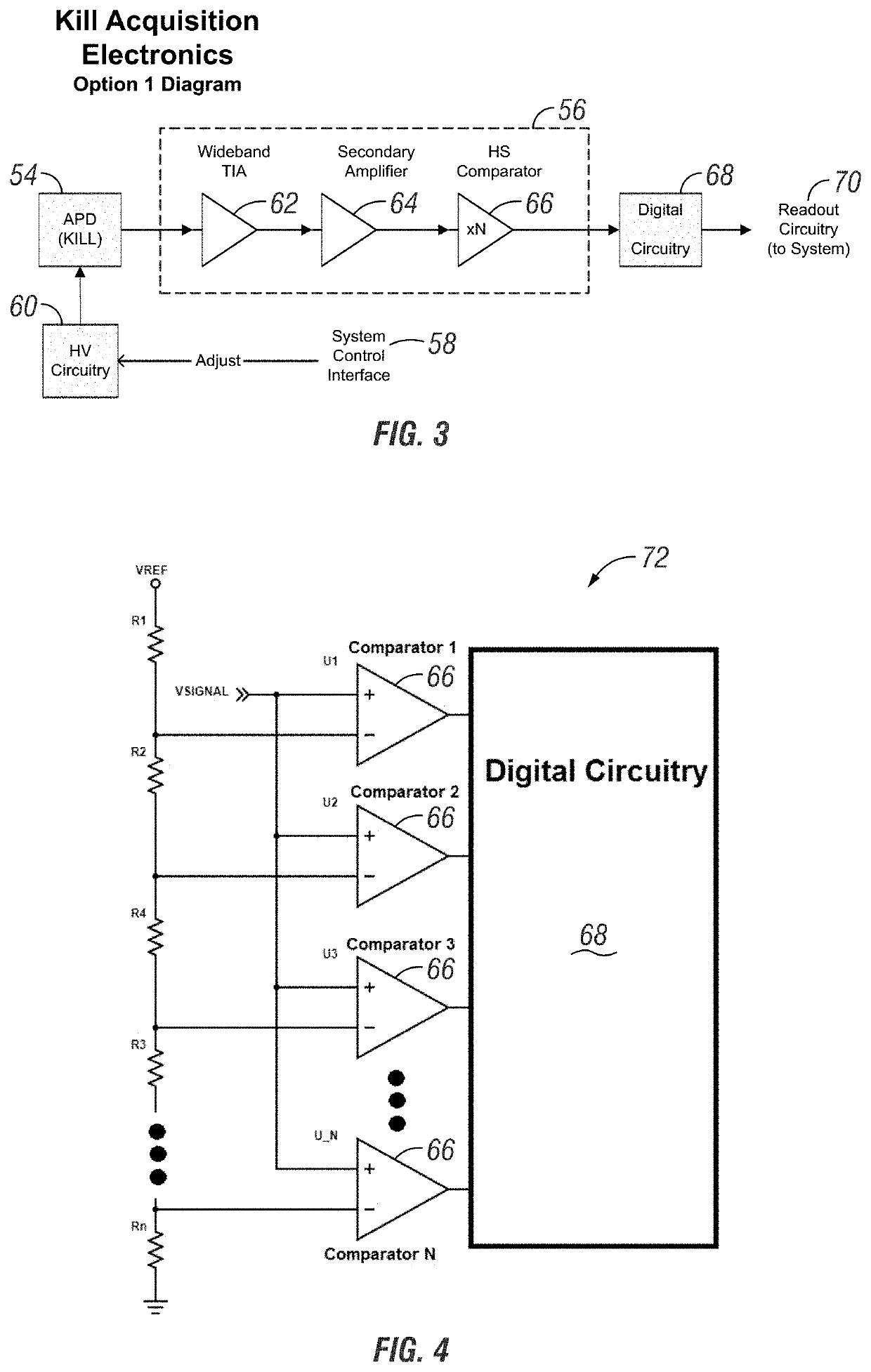
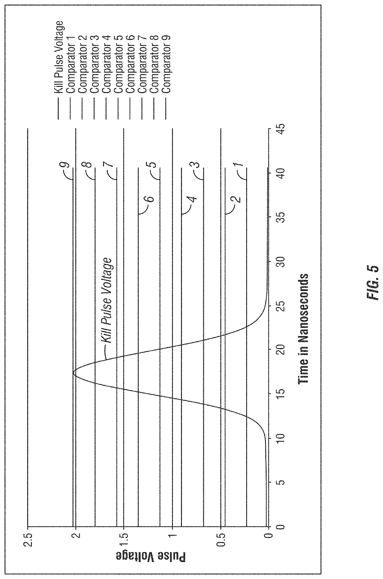
[0081]Reference is made to the accompanying drawings which form a part hereof, and in which is shown by way of illustration specific embodiments in which the invention may be practiced. These embodiments of the invention will be described in detail with reference to the drawings, wherein like reference numerals represent like parts throughout the several views. These embodiments are described in sufficient detail to enable those skilled in the art to practice the invention and it is to be understood that other embodiments may be utilize...


PUM

PropertyMeasurementUnit
heightaaaaaaaaaa
widthaaaaaaaaaa
fluorescenceaaaaaaaaaa

Abstract

A method and related apparatus for confirming whether a kill laser successfully destroys an undesired population of cells includes introducing fluorescent dye into cells, exciting the cells with a detection laser or a light emitting diode to cause the cell to fluoresce for a first time, measuring the amount of fluorescence in the cells with a detector capable of emitting a detection pulse, classifying the cells via embedded processing as undesired or desired cells based on the amount of fluorescence, firing a kill beam with a kill laser at any undesired cells, measuring the amount of fluorescence in the cells a second time to determine whether a fluorescent event was generated from the kill beam striking the cells, and providing feedback to an operator of the kill laser as to whether any fluorescent events were generated from the kill beam striking the cells.

Description

FIELD OF THE INVENTION[0001]The present disclosure relates generally to an optical signal measurement method and apparatus for fluorescence signal confirmation in biotechnology. More particularly, the present disclosure relates to an apparatus and method for confirming whether a kill laser operating in the same, nearly the same, or different wavelength as a detection pulse and using high intensity ultraviolet irradiation successfully destroys an undesired population of sexed cells by measuring for an abrupt energy pulse created during a kill through the use of one or more luminescent dyes.BACKGROUND OF THE INVENTION[0002]Sexed semen (i.e. semen samples wherein the intact, fertile sperm cells are predominantly either X-chromosome bearing or Y-chromosome bearing) is important in a number of applications and industries. High purity sperm cell populations that have been differentiated based on chromosomal differences—such as, for example, sperm cell populations that are skewed toward X-...

Claims


Application Information

Patent Timeline
Patent Type & Authority Applications(United States)
IPC IPC(8): C12N5/00G02B21/16G01N21/64
CPCC12N5/0093G01N21/6456G02B21/16G01N2021/646G01N15/14G01N2015/1006G01N2015/149G01N15/1459G01N15/147
Inventor SAVAGE, FREDERICK HERSHELAPPLEYARD, DAVIDXIA, ZHENGEBERSOLE, MATTHEWMCADA, DANIEL
Owner ABS GLOBAL
Why Eureka
Try Eureka