Array with light emitting diodes and varying lens

a technology of light-emitting diodes and arrays, which is applied in the direction of instruments, lighting and heating apparatus, semiconductor devices for light sources, etc., can solve the problem that the use of space constraints is not generally acceptable for a large area, and achieve the effect of reducing the lateral area

Active Publication Date: 2019-12-19
LUMILEDS
View PDF3 Cites 12 Cited by
  • Summary
  • Abstract
  • Description
  • Claims
  • Application Information

AI Technical Summary

Benefits of technology

[0003]It is an object of the present invention to provide a light emitting diode (LED) array module with reduced lateral area which is especially suited for a flash light of a mobile phone.
[0006]The common lens segment enables a reduction of lateral size in comparison to lens arrays in which different lens segments are assigned to respective LEDs. The lens may be, for example, a Fresnel lens or a partial TIR lens or a combination thereof. It may especially be preferred that the Fresnel lens is a catadioptric Fresnel lens. The sections may be ring structure arranged around the axis or may only comprise a sector of such a ring structure. The ring structure may be preferably rotationally symmetric (e.g. circular, or any kind of discrete rotational symmetry like elliptical, quadratic shapes etc.) in case of a closed ring structure. The sections of the common segment are arranged such that flux emitted by one of the LEDs is predominantly imaged to the respective target area in order to enable a homogeneous illumination of a scene. The respective target area therefore receives substantially more of the flux of the respective LED in comparison to target areas surrounding the respective target area. The lens is therefore arranged such that the contrast of light distribution is increased by making sure that the light received from the LED by the respective target area is increased in comparison to the light received by the surrounding target areas from the same LED. The sections provide a varying profile (uneven surface) wherein the profile may depend on the distance of the section to the axis.
[0018]The lens and especially the sections enable an increased contrast between the respective target area and target areas assigned to other than the at least one light emitting diode which are arranged around the respective target area. It may be preferred that the respective target area receives at least 30% of the flux received by all target areas in the reference plane and wherein the flux received by the respective target area is at least 170% or even 200% of the flux received by any of the surrounding or neighboring target areas.

Problems solved by technology

This larger area is not generally acceptable for space constrained uses such as mobile phones flash systems.

Method used


Image

  • Array with light emitting diodes and varying lens
  • Array with light emitting diodes and varying lens
  • Array with light emitting diodes and varying lens

Examples


first embodiment

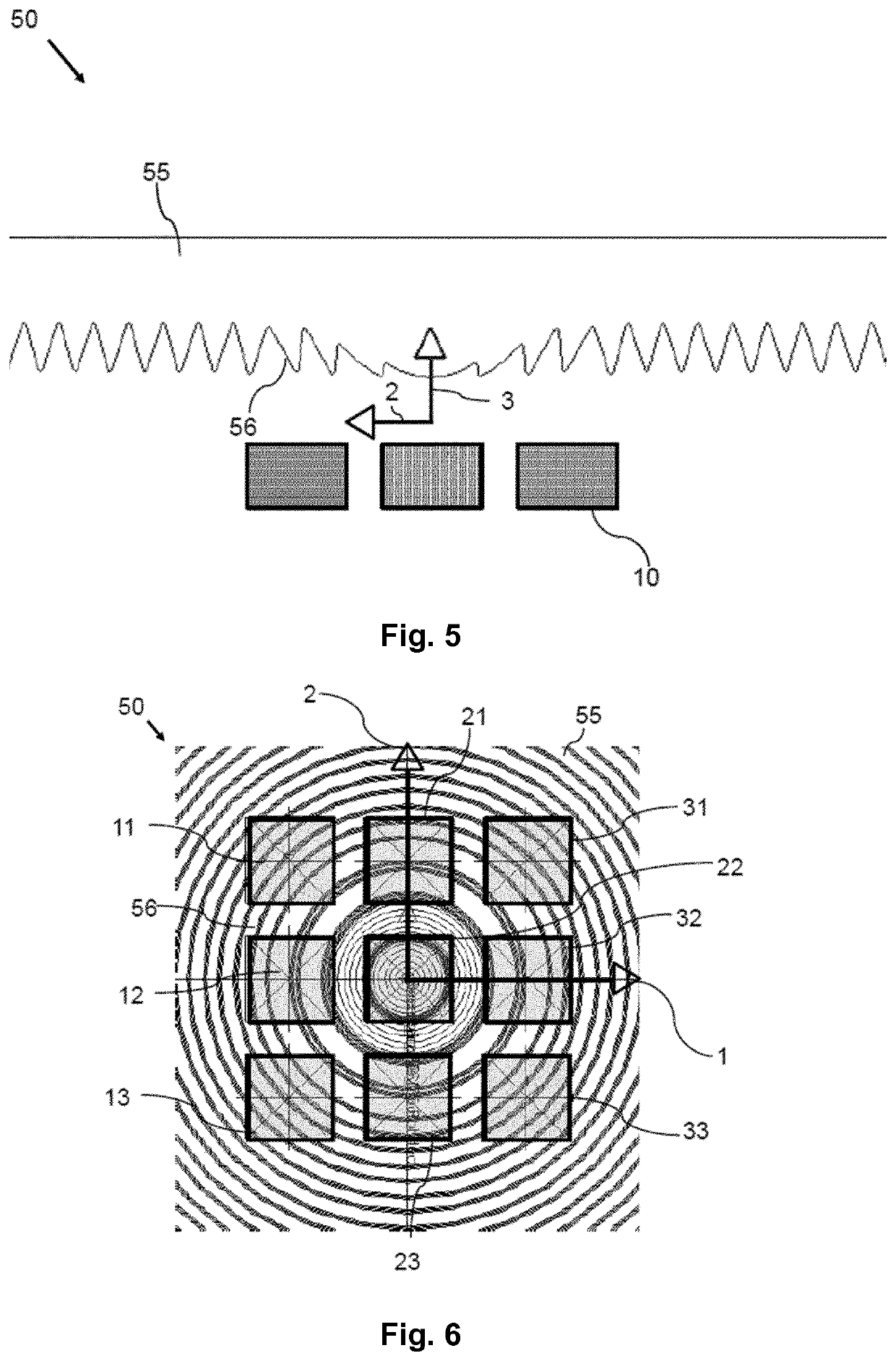
[0043]FIG. 5 shows a principal sketch of a cross-section of a LED array module 50. The general configuration is similar to the configuration discussed with respect to FIG. 1. The LED array module 50 comprises in this case a lens 55 which is a Fresnel type lens comprising a multitude of rotational symmetric sections 56 (see FIG. 6) arranged around an axis, wherein the axis is in this case identical with the z-axis 3. The sections shape or provide an uneven surface of the lens 55, wherein the uneven surface is in this embodiment arranged near to the LEDs 10. Each section 56 (besides of the center section) comprises an inner side surface arranged nearer to the axis and an outer side surface arranged farer from the axis. The inner side surface is joined with the outer side surface by a peak. The cross-section of the uneven surface therefore comprises saw tooth like structures. The orientation of the saw tooth with respect to the axis changes within a defined range from the axis in order...

second embodiment

[0049]FIG. 10 shows a principal sketch of a cross-section of the LED array module 50. The LED array module 50 comprises an array of 3×5 LEDs 10 wherein the cross-section is taken across the third row of the array of LEDs 10. The sections 56 are closed and elliptical in a top view (not shown) in order to enable a homogeneous light distribution in the reference plane and especially a homogeneous illumination of the intended scene. The inner side surface of the outer sections 56 (sections 5-14 counting from the middle or center of lens 55) are straight similar as discussed with respect to FIG. 5. The outer side surfaces of outer sections 56 are curved. The inner side surface, the peak and the outer side surface define a triangular cross section (connecting the endpoints of the inner side surface and the outer side surface away from the peak with a straight-line) in which the sum of the internal angles is bigger than 180°. The curvature may be adapted in accordance with the intended lig...


PUM


Abstract

The invention describes a light emitting diode array module comprising at least two light emitting diodes and a lens, wherein the lens comprises one common lens segment, wherein the common lens segment comprises a multitude of sections at least partly encompassing an axis perpendicular to the lens, wherein the sections shape an uneven surface of the lens, wherein the light emitting diodes are arranged to illuminate at least two non-overlapping target areas in a reference plane, and wherein the sections are arranged such that at least one light emitting diode illuminates one respective target area of the target areas. The invention further describes a flash light comprising at least one light emitting diode array module.

Description

FIELD OF THE INVENTION[0001]The invention relates to an array with light emitting diodes and varying lens. The invention further relates to a flash light comprising one or more of the LED array modules.BACKGROUND OF THE INVENTION[0002]Adaptive flash needs higher beam shaping control than conventional flash in order to direct flux into specific areas of the scene. One way to achieve this is to have an array of small LEDs and different optics per LED (array of lenses). While this might keep thickness small, it requires larger lateral area to accommodate all the lenses. This larger area is not generally acceptable for space constrained uses such as mobile phones flash systems.SUMMARY OF THE INVENTION[0003]It is an object of the present invention to provide a light emitting diode (LED) array module with reduced lateral area which is especially suited for a flash light of a mobile phone.[0004]The invention is described in the independent claims. The dependent claims comprise preferred em...

Claims


Application Information

Patent Timeline
Patent Type & Authority Applications(United States)
IPC IPC(8): F21V5/04H01L33/58H01L27/15F21L4/02
CPCF21V5/045H01L27/156H01L33/58F21Y2115/10F21L4/027F21L4/00F21Y2105/14G02B19/0028G02B19/0066G02B3/08G02B17/006G03B15/05G03B2215/0592G03B2215/0567F21S2/005H01L27/14627
Inventor VAN DER SIJDE, ARJENPFEFFER, NICOLASTASSAR, EMANUEL NICOLAAS HERMANUS JOHANNES
Owner LUMILEDS
Why Eureka
Try Eureka