Stand-alone continuous cardiac doppler and acoustic pulse monitoring patch with integral visual and auditory alerts, and patch-display system and method

a cardiac doppler and acoustic pulse technology, applied in the field of stand-alone continuous cardiac doppler and acoustic pulse monitoring patch, can solve the problems of difficult physical palpitation of pulse, high time sensitive decision to initiate cpr or other procedures to treat cardiac arrest, and high cost, and achieves fast and reliable means of detection. , the effect of less expensiv

Active Publication Date: 2019-12-26
PHAM & RODRIQUEZ INNOVATIONS LLC
View PDF0 Cites 7 Cited by
  • Summary
  • Abstract
  • Description
  • Claims
  • Application Information

AI Technical Summary

Benefits of technology

[0011]The present invention discloses a stand-alone continuous cardiac Doppler and acoustic pulse monitoring patch that provides visual and auditory signals that a pulse is detected or not detected in a subject. The invention is a small patch with a peel-away adhesive surface that is applied to the skin of a subject. The Doppler monitor should be applied near a large artery and the acoustic monitor should be applied over the heart. The adhesive surface of the patch secures the monitor to the skin of the patient and also includes a layer of material, such as gel, to provide a conductive medium for the Doppler monitor, to enhance transmission and reception of ultrasonic waves, or sound isolation for the acoustic monitor, to enhance reception of heartbeats and insulate against or absorb unwanted sounds. The patch includes a power source, electronics associated with the Doppler or acoustic signals, a processor to control and analyze the signals, a memory, and one or more of a light, speaker, or vibration generator to indicate the presence and strength of a pulse.
[0015]In an alternative embodiment, an integrated continuous cardiac Doppler or acoustic pulse monitoring patch includes a port to connect the patch by conductive wires to a separate display unit that can receive the blood flow and pulse data from the patch and display the data visually on a screen as well as provide auditory or vibratory signals. The display unit can further process the data and display heart pulse (bpm) and blood flow (cm / s) rates in numerical and graphic forms. In a further embodiment, the patch and display unit can each include wireless transceivers to connect them and communicate the data wirelessly. In yet a further embodiment, the display unit can provide processing and power for the patch, which is consequently simplified and less expensive. In another embodiment, a simplified patch will have transducers to transmit and receive ultrasound waves and its own integrated power and wireless communication capability, thereby allowing the simplified patch to provide Doppler or acoustic signal data wirelessly to the display unit, which will process and display the data.

Problems solved by technology

The decision to initiate CPR or other procedures to treat cardiac arrest is highly time sensitive.
But, the physical palpitation of a pulse, usually by placing one or more fingers over a subject's artery, is difficult and subject to substantial error.
The use of an electrocardiograph (ECG) to detect a pulse is common, but problematic, because the widely-recognized graphical pattern measures electrical emissions from the heart muscle.
But, these electrical signals detected by the ECG do not measure the flow of blood in the subject and it is not uncommon for telemetry to detect favorable electrical emissions from the heart, even after the flow of blood has ceased and, in some instances, the subject has perished.
As noted above, physical palpitation for a pulse is widely used, but is also substantially unreliable.
But, such a device must be held by a technician and cannot be secured in place to provide constant, real-time information.
For example, when CPR is administered, a hand-held Doppler monitor cannot be held in place without another technician and, even if another technician is available to hold the monitor in place, the movement of the patient undergoing CPR makes holding the wand in place and receiving useful return signals is extremely difficult.
As with the Doppler monitors, these acoustic stethoscopes must be held in place and a separate display must be observed to see the heartbeat waveform, making it awkward to administer CPR while continuing to monitor real-time information.
Even in the hospital setting existing devices pose problems.
As noted above, since the passage of even very short periods of time can drastically reduce the chance of survival from cessation of blood flow, the lack of direct information can be a significant contributor to mortality.
Identifying and tracking the mechanical blood flow of the heart and large arterial vessels in real time is underutilized and important.
The current system of isolated finger pulse or Doppler pulse checks is challenging, even for medical professionals.

Method used


Image

  • Stand-alone continuous cardiac doppler and acoustic pulse monitoring patch with integral visual and auditory alerts, and patch-display system and method
  • Stand-alone continuous cardiac doppler and acoustic pulse monitoring patch with integral visual and auditory alerts, and patch-display system and method
  • Stand-alone continuous cardiac doppler and acoustic pulse monitoring patch with integral visual and auditory alerts, and patch-display system and method

Examples


Embodiment Construction

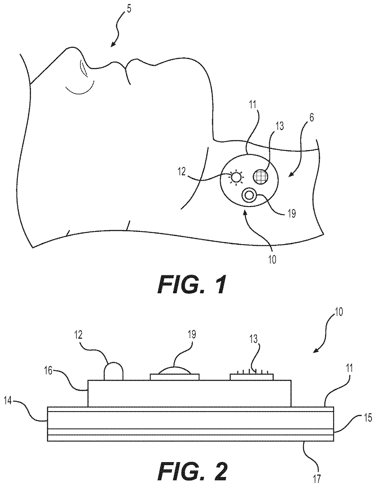
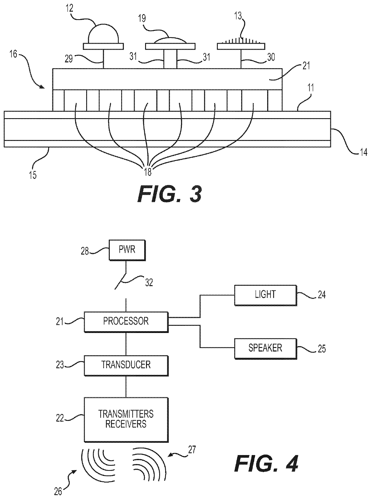
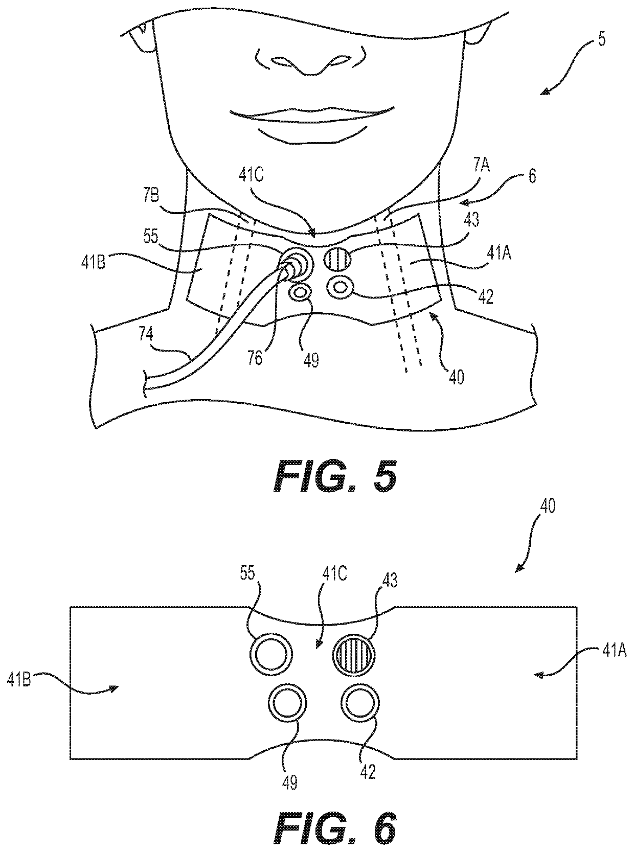
[0039]FIG. 1 shows the stand-alone continuous Doppler heart monitor patch 10 applied to the side of the neck of a patient 5. In this position, the monitor 10 will be close to the subject's neck artery 6, the right common carotid artery 7B shown in FIG. 5, which is one of the better arteries for detecting a pulse. The carotid artery is a useful position to detect pulse, since it leaves the subject's chest free for CPR or other procedures to address cardiac arrest. The monitor 10 may be placed over other arteries, such as the femoral or radial arteries. When the on / off switch 19 is turned to the on position, the monitor 10 is placed over the subject's neck artery 6 and will begin transmitting ultrasonic signals and detecting their reflections. When blood is flowing, the Doppler effect on the reflected signals will be identified by the monitor's 10 circuitry (16 in FIGS. 2 and 3), described below, as indicative of the blood's flow velocity, as well as of the frequency of pulses as puls...


PUM


Abstract

A stand-alone continuous cardiac Doppler or acoustic pulse monitoring patch provides visual and auditory signals that a pulse or heartbeat is detected or not detected in a human subject. The invention is a small patch with a peel-away adhesive surface that is applied to the skin of the subject, preferably near a large artery. For the Doppler monitor, the patch includes a pad formed of a conductive medium to enhance transmission and reception of ultrasonic waves. For the acoustic monitor, the pad has a sound focusing portion that permits entry of sounds and focuses the sounds toward a microphone, and the pad also has a sound insulating portion surround the sound focusing portion. The patch includes an integral power source. The Doppler patch has transmitters and receivers to send and detect reflected ultrasonic waves and a transducer to convert the reflected waves into an electrical signal. The acoustic patch has a microphone to detect the sound of a heartbeat and a transducer to convert the sound energy into an electrical signal. A processor analyzes the Doppler wave signals or the acoustic signals. A light indicates the presence and strength of a pulse detected from the Doppler wave signals or a heartbeat detected by the microphone. A speaker and a vibrator may also to indicate the presence and strength of a pulse or a heartbeat. The Doppler effect of waves reflecting from blood pumped from a heart is used to detect a pulse in the subject. The presence of a pulse or heartbeat is analyzed by the processor to determine the frequency and strength of blood flow or beating of the heart. The processor causes the light, speaker or vibrator to blink, beep or vibrate at a rate to indicate the frequency of rhythmic blood flow or heartbeat.

Description

CLAIM OF PRIORITY TO NON-PROVISIONAL AND PROVISIONAL APPLICATIONS (35 U.S.C. §§ 120 AND 119(E))[0001]Pursuant to 35 U.S.C. § 120 and 37 CFR 1.78(d)(2), this application is a continuation-in-part of prior non-provisional patent application Ser. No. 15 / 834,044 filed on Dec. 6, 2017 (“the '044 Non-Provisional application”). The '044 Non-Provisional application claimed priority, under 35 U.S.C. § 119(e), from provisional patent Application No. 62 / 430,872 filed on Dec. 6, 2016, and from provisional application No. 62 / 523,765 filed on Jun. 22, 2017. Accordingly, this continuation-in-part application is entitled to the benefit of these provisional applications. The Ser. No. 15 / 834,044 non-provisional application and the 62 / 430,872 and 62 / 523,765 provisional applications are incorporated herein by reference.FIELD OF THE INVENTION[0002]The present invention relates to a stand-alone continuous cardiac Doppler and acoustic pulse monitoring patch that provides visual and auditory signals that b...

Claims


Application Information

Patent Timeline
Patent Type & Authority Applications(United States)
IPC IPC(8): A61B8/00A61B5/00A61B8/02A61B8/06A61B8/08
CPCA61B8/4236A61B8/4281A61B8/02A61B5/6833A61B8/065A61B8/488A61B5/742A61B8/56A61B8/0866A61B5/026A61B7/02A61B8/06
Inventor RODRIQUEZ, GERARDO
Owner PHAM & RODRIQUEZ INNOVATIONS LLC
Why Eureka
Try Eureka