Lightning protection arrangement

a technology for protecting the rotor blade and the lightning protection arrangement, which is applied in the direction of wind turbines, engine components, wind energy generation, etc., can solve the problems of affecting the lightning protection effect of the blade, the blade is generally most vulnerable to lightning strikes, and the prior art receptor is compromised, etc., to achieve the effect of minimizing the impact of blade aerodynamic performance, low profile and effective withstand

Active Publication Date: 2019-12-26
SIEMENS GAMESA RENEWABLE ENERGY AS
View PDF0 Cites 2 Cited by
  • Summary
  • Abstract
  • Description
  • Claims
  • Application Information

AI Technical Summary

Benefits of technology

[0022]The current passing through a trailing edge receptor will cause it to become very hot, and any surrounding material of the rotor blade will be heated also. The trailing edge is generally the thinnest part of the airfoil. For some types of blade and / or towards the tip region of the blade, the thickness of the blade at the trailing edge may be only a few millimetres. Therefore, in a preferred embodiment of the invention, when the trailing edge receptor is embedded in such a thin trailing edge, the thickness of the rotor blade is augmented around the trailing edge receptor. This can be visualized as a “bulge” enclosing the embedded portion of the trailing edge receptor. The bulge can be formed to present a low profile in order to minimize its impact on the blade's aerodynamic performance, and can effectively withstand the heat resulting from a lightning strike
[0023]With the inventive lightning protection arrangement, the performance of the rotor blade's LPS can be significantly improved by the improved attractiveness of the trailing edge receptor, and the lifetime of the rotor blade can be favourably extended. In a preferred embodiment of the invention, particularly in the case of very long rotor blades, the lightning protection arrangement can comprise two terminals and two trailing edge receptors arranged to point outward into the air behind the trailing edge. In this preferred embodiment, a first terminal is arranged as close as possible to the blade tip, and the second terminal is arranged further inward from the blade tip. In this way, lightning damage to even a very long blade can be effectively minimized, thereby extending its lifetime and reducing maintenance costs.
[0024]In another preferred embodiment of the invention, a trailing edge receptor may be connected to the existing receptor of a conventional single-receptor terminal. For example, a rotor blade lightning protection arrangement may comprise a puck-shaped receptor set into one side of the rotor blade (on the suction side or on the pressure side). This conventional receptor extends through the blade body to connect to the terminal, and can be effective at receiving lightning strikes when the wind turbine blades are stationary. In a retrofitting step, this receptor can be adapted to receive a trailing edge receptor which extends from the receptor along the surface of the blade and outward beyond the trailing edge of the blade. In such a retrofit embodiment of the invention, the existing lightning attractor is “upgraded” by mounting the trailing edge receptor to it. The performance of the existing LPS can be improved by the trailing edge receptor, since it protrudes into the ion cloud that follows in the wake of a blade's trailing edge when the wind turbine blades are rotating.

Problems solved by technology

With increasing tower height and blade length, particularly in the case of offshore wind turbines, the blades are generally most vulnerable to lightning strikes.
Also, in geographical regions with a high incidence rate of electrical storms, even the blades of a wind turbine of relatively moderate height can be exposed to many lightning strikes per year.
The effectiveness of a prior art receptor is therefore compromised by the rotation of the blades, which results in the receptor being less than optimally placed in the ion cloud.
Therefore, the problem of the displaced ion cloud and reduced receptor efficiency cannot be remedied by simply moving the prior art receptor laterally towards the thinner trailing edge region of the blade, since this would expose most of its bulk, which would greatly interfere with the aerodynamic performance of the blade.
Furthermore, there are structural risks associated with the prior art receptor since this is embedded in the rotor blade to essentially lie flush with the blade surface.
This heat damage can result in cracks, which in turn permit moisture to enter.
Any moisture present under the blade skin in this region can result in a steam explosion in a subsequent lightning strike.
Blade failure and / or expensive repair work may ensue from this type of damage.

Method used


Image

  • Lightning protection arrangement
  • Lightning protection arrangement
  • Lightning protection arrangement

Examples


first embodiment

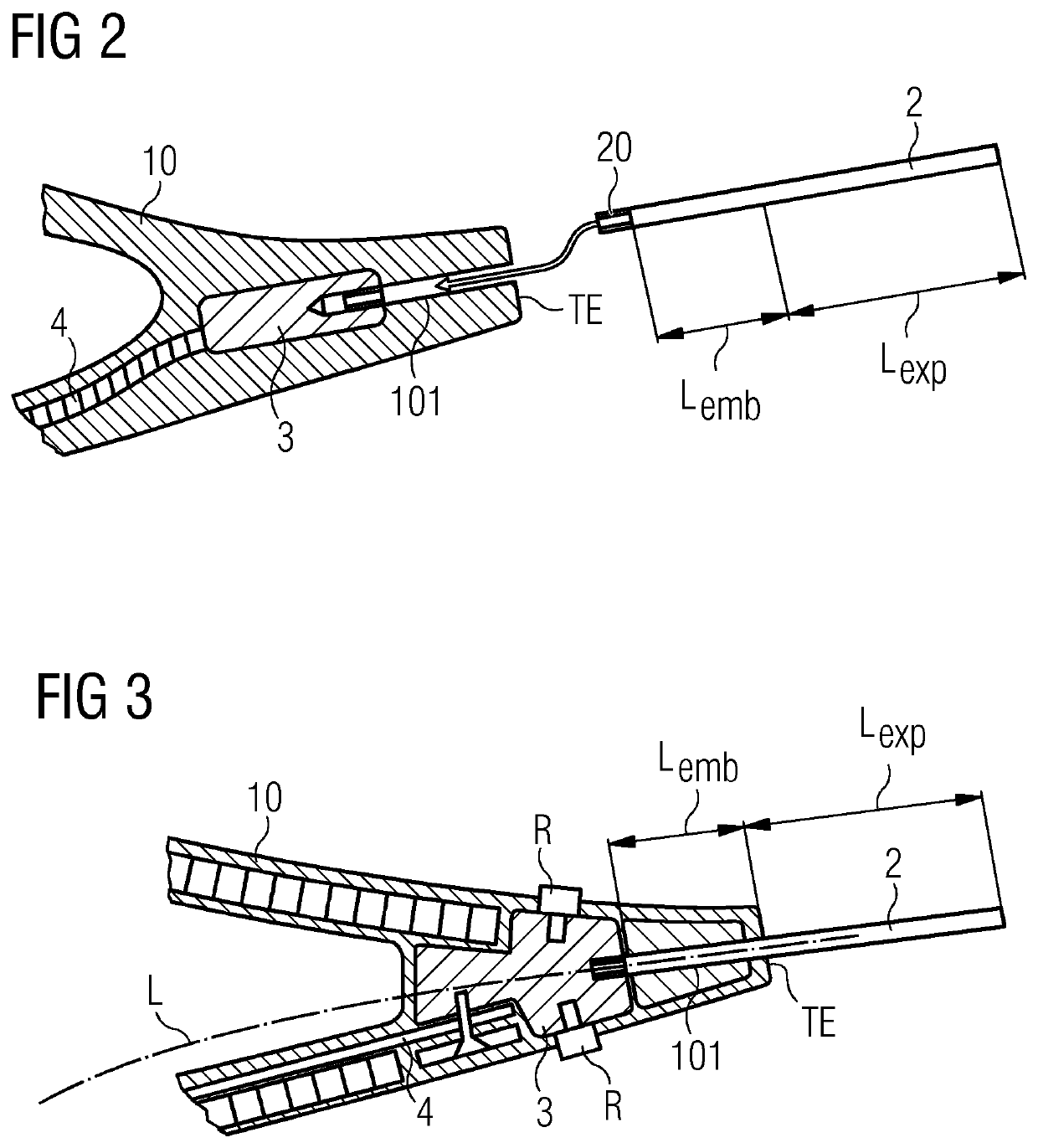
[0043]FIG. 2 is a cross-section through a rotor blade 10 and shows a trailing edge receptor 2 of the inventive lightning protection arrangement. The trailing edge receptor 2 is formed as a rod or bar, with a threaded end 20 for connecting to a terminal 3 in the interior of the blade 10. A portion of the trailing edge receptor 2 with length Lexp will be exposed in the air behind the trailing edge TE, and a remaining portion with length Lemb will be embedded in the blade 10. The exposed length Lexp preferably extends over at least 10 mm, more preferably over at least 50 mm. The diameter of a rod-shaped trailing edge receptor 2 is preferably in the order of 8 mm, for a favourable cross-sectional area of at least 50 mm2 so that the trailing edge receptor 2 can safely carry the high current of a lightning strike.

[0044]The terminal 3 is connected in any suitable manner to a down conductor 4 as part of the blade-to-ground current path of the wind turbine's LPS, and this established configu...

second embodiment

[0045]FIG. 3 is a cross-section through a rotor blade 10 and shows a trailing edge receptor 2 of the inventive lightning protection arrangement. In this case also, the trailing edge receptor 2 is formed as a rod or bar, with a threaded end 20 for connecting to a terminal 3 in the interior of the blade 10, and a channel 101 has been provided in the trailing edge region of the blade 10 to receive the trailing edge receptor 2. The diagram shows that the channel 101 has been formed to lie more or less along the camber line L of the blade 10, so that the trailing edge receptor 2 will act as an extension of the camber line L.

[0046]Here also, a portion of the trailing edge receptor 2 with length Lexp is exposed in the air behind the trailing edge TE, and a remaining portion with length Lemb is embedded in the blade 10. In this embodiment, prior art receptors R are located on the suction side and pressure side of the blade 10. This realization may therefore be a retro-fit embodiment of the ...


PUM


Abstract

Provided is a lightning protection arrangement of a wind turbine rotor blade, including at least one terminal connected to a down conductor arranged in the blade interior and a number of lightning attractors electrically connected to the terminal; and wherein at least one lightning attractor includes an interior connector for making electrical contact to the terminal; and a trailing edge receptor arranged to extend beyond the trailing edge of the rotor blade in a direction opposite to the direction of travel of the rotor blade A wind turbine rotor blade including, a lightning protection arrangement, a method of equipping a wind turbine rotor blade with such a lightning protection arrangement is also provided.

Description

CROSS-REFERENCE TO RELATED APPLICATIONS[0001]This application claims priority to PCT Application No. PCT / EP2017 / 078778, having a filing date of Nov. 9, 2017, based off of German Application No. 10 2017 201 093.2 having a filing date of Jan. 24, 2017, the entire contents both of which are hereby incorporated by reference.FIELD OF TECHNOLOGY[0002]The following relates to d a wind turbine rotor blade lightning protection arrangement; a wind turbine rotor blade; and a method of equipping a wind turbine rotor blade with a lightning protection arrangement.BACKGROUND[0003]A wind turbine is generally equipped with a lightning protection system (LPS) to minimize or avoid damage during a lightning strike. A lightning strike can occur at any exposed part of the wind turbine, and these are generally equipped with specialized arrangements of receptors and down conductors. With increasing tower height and blade length, particularly in the case of offshore wind turbines, the blades are generally m...

Claims


Application Information

Patent Timeline
Patent Type & Authority Applications(United States)
IPC IPC(8): F03D80/30F03D1/06
CPCF03D80/30F03D1/0675F05B2240/30Y02E10/72
Inventor DAHL, FLEMMINGNIELSEN, MOGENS
Owner SIEMENS GAMESA RENEWABLE ENERGY AS
Why Eureka
Try Eureka