Geothermal system operable between heat recovery and heat storage modes

a geothermal system and heat storage technology, applied in geothermal energy generation, domestic heating, light and heating apparatus, etc., can solve the problems of difficult control of the connection zone between the wells, high cost of drilling the wells, and difficulty in properly connecting the two wells at depth, so as to improve the overall efficiency of heat recovery throughout the thermal storage and recovery process, and recover heat

Inactive Publication Date: 2020-01-09
GRAHAM PETER SAMUEL WINSTON +1
View PDF0 Cites 20 Cited by
  • Summary
  • Abstract
  • Description
  • Claims
  • Application Information

AI Technical Summary

Benefits of technology

[0022]Preferably the inner pipe is partially to totally insulated along its length to minimize heat losses from the ascending heat exchanger fluid.
[0023]The heat storage mode described herein works together with the heat recovery mode so that the overall efficiency of heat recovery throughout the thermal storage and recovery process is improved. The method can recover heat at a temperature adequate for space heating and other uses without the need of supplemental heat from other sources.
[0024]The invention uses the previously developed single well coaxial pipe heat exchanger technology. The inventive nature of this Application is to include several equipment and operational modifications to significantly increase the amount of recoverable heat, and also increase the recoverable temperature at surface. These equipment and operational changes can also significantly reduce capital and operating costs.
[0027]In the first mode, heat loss from the piping at the surface is minimized, using insulation and / or by diverting flow to minimize the length of the flow path between the inner and outer pipes.
[0030]The method may further include expanding the rock material in the ground source surrounding the outer pipe by transferring heat into the ground source along the upper portion of the outer pipe for closing fissures and other permeable conduits in the rock material and for preventing upward migration of formational fluids and gasses in the ground source.

Problems solved by technology

The cost of drilling the wells is high, and the success rate of properly connecting the two wells at depth can be relatively low.
Further, the connected zone between the well pairings is difficult to control as there are fluid losses in to the rock formations.
In this case a significant amount of pumping is required to counteract the fluid loss.
The greatest drawback of the single aquifer pumping well method is when there is less than adequate water recharge from the aquifer.
Furthermore, the fluid returned to the surface may contain high levels of noxious contaminants which have to be disposed of safely.
Formational water can also be corrosive which reduces the life expectancy of the pipes and pumps.
The disadvantage of this heat exchanger technology is the significantly reduced amount of heat recovered.
Technically it is difficult to achieve sufficient water residence time for boreholes less than 178 mmm diameter.
Further, the higher the flow velocity of the injected water reduces the residence time which reduces the amount of heat recovered.
There are two key factors that limit the economics of the coaxial well technology.
The first factor is the high cost and the space restrictions of the insulated inner pipe.
The second factor is the restricted heat recovery due to the shortened residence time of the fluid during the heat transfer process.
Although the heat exchange technology has significant environmental benefits, low heat productivity and high capital costs have prevented this technology from flourishing.

Method used


Image

  • Geothermal system operable between heat recovery and heat storage modes
  • Geothermal system operable between heat recovery and heat storage modes

Examples


Embodiment Construction

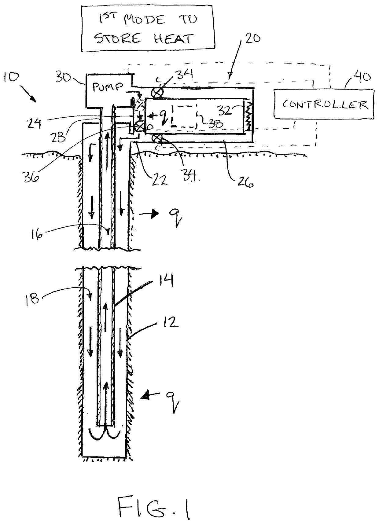
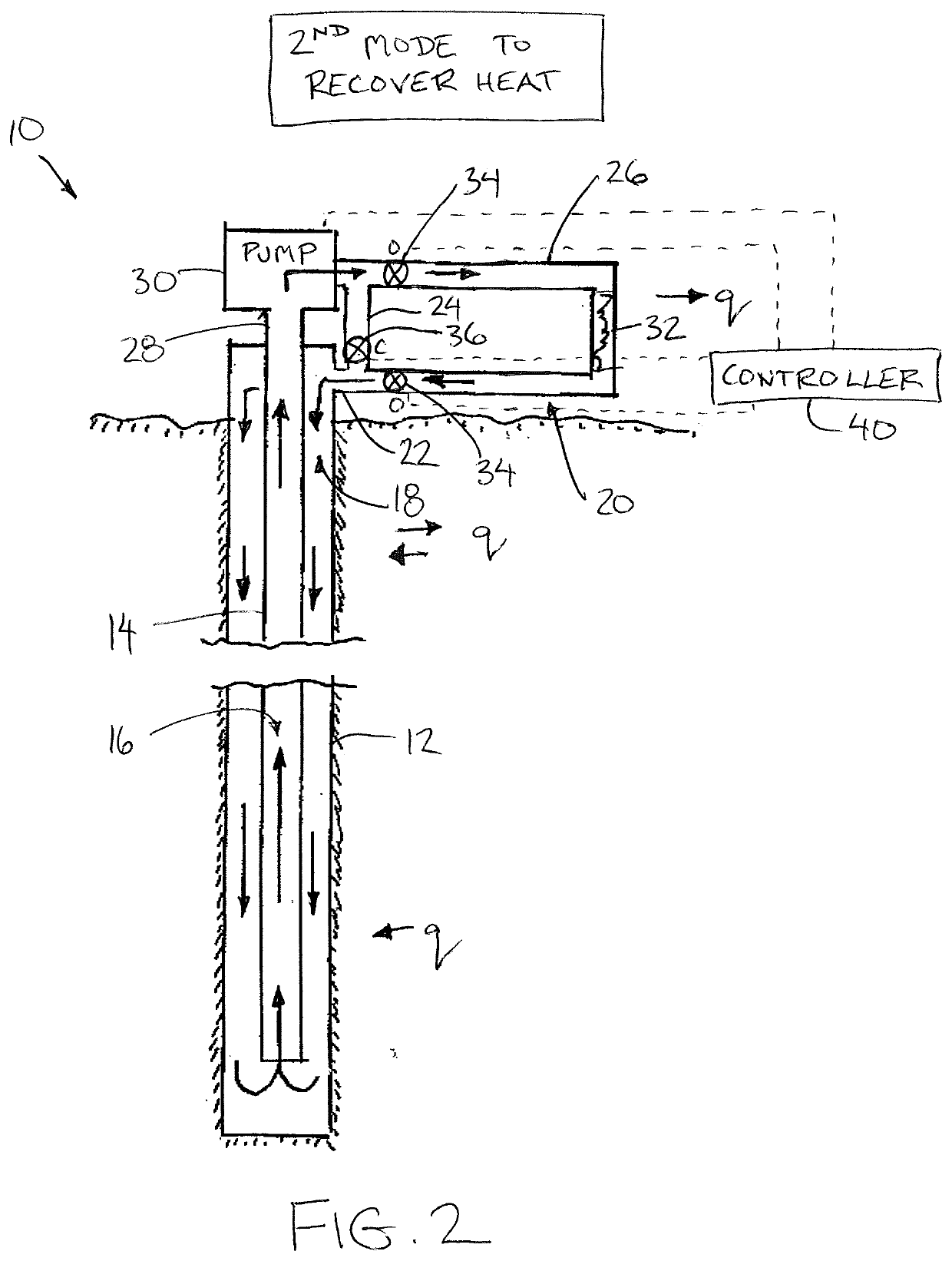
[0044]Referring to the accompanying figures there is illustrated a geothermal system 10 installed in the ground such that the ground is used as a heat source and / or heat sink. In the illustrated embodiment, the geothermal system is installed within a reclaimed hydrocarbon wellbore in which the existing well casing of the wellbore defines an outer pipe 12. The well casing is plugged at a location above a production zone of the wellbore to define a bottom end of the outer pipe 12 such that the outer pipe extends longitudinally downward from a top end at a surface of the ground heat source to the bottom end which is closed. Alternatively, any borehole formed in the ground and lined with an outer pipe may be used.

[0045]An inner pipe 14 is installed within the outer pipe 12 in which the inner pipe has an outer diameter which is less than the inner diameter of the outer pipe so as to define an annular space between the inner and outer pipes extending along the length of the pipes. The inn...


PUM


Abstract

The geothermal system uses an outer and an inner pipe installed in a single borehole. Cool fluids are pumped down through one pipe and returned to the surface through the other pipe. Subterranean heat increases the temperature of the cool fluid and this heat is returned to the surface where the heated fluid is recovered. The fluid with the heat removed is then pumped back down the borehole to be re-heated. Extra heat recovered from the ground surrounding a lower portion of the borehole is stored in the ground and rock formation surrounding an upper portion of the borehole during warmer seasons to optimize the amount of heat stored in the ground for extraction during colder seasons.

Description

[0001]This application claims the benefit under 35 U.S.C. 119(e) of U.S. provisional application Ser. No. 62 / 693,939, filed Jul. 4, 2018.FIELD OF THE INVENTION[0002]The present invention relates to the recovery of heat from a geothermal system including a well in the ground from which heat is extracted, and more particularly the present invention relates to a geothermal system which is seasonal varied between a heat recovery mode in which heat is drawn out of the geothermal well and a heat storage mode in which heat is stored in the geothermal well.BACKGROUND[0003]Below the Earth's surface, temperature increases with depth. The rate of temperature increase, or geothermal gradient typically ranges between 2 and 3° C. per 100 metres of depth. However, in some regions, the gradient can be significantly higher with very hot temperatures found closer to the Earth's surface. Current technologies are exploiting some of these near surface hot spots for electrical power generation and heatin...

Claims


Application Information

Patent Timeline
Patent Type & Authority Applications(United States)
IPC IPC(8): F24T10/10
CPCF24T10/10F24T10/17F24T2010/56F24T50/00Y02E10/10
Inventor GRAHAM, PETER SAMUEL WINSTONSHUNK, BLAIR CAMERON
Owner GRAHAM PETER SAMUEL WINSTON
Why Eureka
Try Eureka