Independently controlled three stage water injection in a diffusion burner

a technology of diffusion burner and independent control, which is applied in the direction of gas turbine plants, machines/engines, mechanical equipment, etc., can solve the problems of system complexity and unwanted stability, and achieve the effects of improving mixing, promoting early formation of water droplets, and increasing the surface energy of the j

Inactive Publication Date: 2020-01-16
SIEMENS ENERGY INC
View PDF0 Cites 0 Cited by
  • Summary
  • Abstract
  • Description
  • Claims
  • Application Information

AI Technical Summary

Benefits of technology

[0007]In accordance with the teachings of the present invention, a turbine engine combustion system is disclosed including a fuel nozzle assembly having three independently controlled stages of water injection. The intent of introducing water through a third stage is to improve mixing of water with other fluids in the combustor basket. The increased interaction between water jets and external aerodynamic forces promotes early formation of water droplets due to increase in the surface energy of the jets which lowers the surface tension. A first stage includes water mixed with a gaseous fuel upon inlet to the nozzle, where the first stage water mixes and travels with the gaseous fuel to be injected into a combustor. A second stage includes water injected into the combustor via a secondary liquid nozzle which is used for fuel oil during liquid fuel operation, but which may be used for the secondary water during gaseous fuel operation. A third stage includes water injected into the combustor via a plurality of orifice nozzle holes collectively known as an atomizing air cap. The atomizing air cap nozzles are used to atomize the fuel during fuel oil operation ignition to improve start up reliability, and can be used for water injection during gaseous fuel operation. An algorithm and criteria are also defined for controlling the three stages of water injection to achieve the optimum balance of turbine operational criteria including NOx emissions, combustion dynamics and water impingement on the combustor basket walls and the transition piece downstream of the nozzle.

Problems solved by technology

However, injecting water can cause unwanted stability problems in the form of high combustor dynamics and durability issues with respect to liner cracking.
The development of such systems requires a delicate balance of these competing design criteria—emissions, dynamics, and hardware life.

Method used


Image

  • Independently controlled three stage water injection in a diffusion burner
  • Independently controlled three stage water injection in a diffusion burner
  • Independently controlled three stage water injection in a diffusion burner

Examples


Embodiment Construction

[0014]The following discussion of the embodiments of the invention directed to three stage water injection in a diffusion burner for a gas turbine engine is merely exemplary in nature, and is in no way intended to limit the invention or its applications or uses.

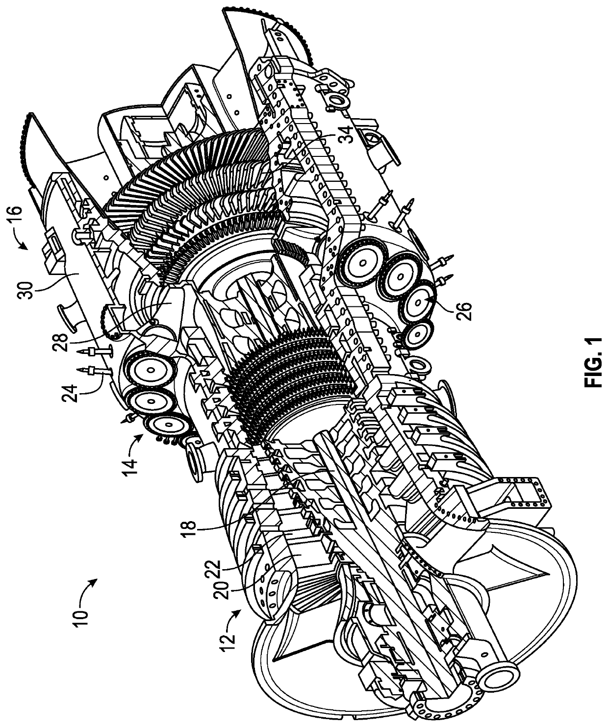
[0015]FIG. 1 is a cutaway, isometric view of a gas turbine engine 10 including a compressor section 12, a combustion section 14 and a turbine section 16 all enclosed within an outer housing or casing 30, where operation of the engine 10 causes a central shaft or rotor 18 to rotate, thus creating mechanical work. The engine 10 is illustrated and described by way of a non-limiting example to provide context to the invention discussed below. Those skilled in the art will appreciate that other gas turbine engine designs can also be used in connection with the invention. Rotation of the rotor 18 draws air into the compressor section 12 where it is directed by vanes 22 and compressed by rotating blades 20 to be delivered to the com...


PUM


Abstract

A turbine engine combustion system is disclosed including a fuel nozzle assembly having three independently controlled stages of water injection. A first stage includes water mixed with a gaseous fuel upon inlet to the nozzle, where the first stage water mixes and travels with the gaseous fuel to be injected into a combustor. A second stage includes water injected into the combustor via a secondary liquid nozzle which is used for fuel oil during liquid fuel operation, but which may be used for the secondary water during gaseous fuel operation. A third stage includes water injected into the combustor via a plurality of nozzle holes known as an atomizing air cap. An algorithm and criteria are also defined for controlling the three stages of water injection to achieve the optimum balance of turbine operational criteria including NOx emissions, combustion dynamics and water impingement downstream of the nozzle.

Description

CROSS-REFERENCE TO RELATED APPLICATIONS[0001]This application is a divisional application of U.S. patent application Ser. No. 14 / 856,973 filed Sep. 17, 2015 which is herein incorporated by reference in its entirety.BACKGROUND OF THE INVENTIONField of the Invention[0002]The invention generally relates to diffusion flame combustors for turbine engines and more particularly to a nozzle system and a method for supplying water in the form of liquid water to such diffusion flame combustors, where the water is provided to the combustor via three independently controlled injection locations in the nozzle.Description of the Related Art[0003]The world's energy needs continue to rise—thus creating a demand for reliable, affordable, efficient and environmentally-compatible power generation. A gas turbine engine is one known machine that provides efficient power, and often has application for an electric generator in a power plant, or engines in an aircraft or a ship. A typical gas turbine engin...

Claims


Application Information

Patent Timeline
Patent Type & Authority Applications(United States)
IPC IPC(8): F02C3/30F02C3/22
CPCF02C3/30F02C3/22
Inventor RODD, SHERVINSINGH, GURDEVDANDWANI, HEENA H.
Owner SIEMENS ENERGY INC
Why Eureka
Try Eureka