Engine controller and engine control method

a technology of engine controller and engine, which is applied in the direction of electric control, machines/engines, output power, etc., can solve the problems of reducing the exhaust performance of the engine, reducing and reducing the detection accuracy of the intake air amount of the airflow meter, so as to improve the calculation accuracy of the first intake air amount and reduce the effect of engine exhaust performan

Active Publication Date: 2020-01-16
TOYOTA JIDOSHA KK
View PDF0 Cites 10 Cited by
  • Summary
  • Abstract
  • Description
  • Claims
  • Application Information

AI Technical Summary

Benefits of technology

[0010]When it is determined in the determination process that the intake pulsation is large (hereinafter referred to as large pulsation determination), the detection accuracy of the intake air amount of the airflow meter is low. Thus, the calculation accuracy of the first intake air amount is low. In the engine controller, the corrected second intake air amount, which is the sum of the second intake air amount and the difference amount calculated when the small pulsation determination is made, is calculated as the calculated value of the intake air amount. That is, at this time, a value obtained by compensating an error in the second intake air amount acknowledged when the small pulsation determination is made is calculated as the calculated value of the intake air amount. Thus, the engine controller improves the calculation accuracy of the intake air amount in a running region where the intake pulsation is large.
[0011]The difference amount between the first intake air amount and the second intake air amount changes depending on, for example, the running region of the engine, the individual difference of the engine, and changes over time. Thus, in the difference amount calculation process in the engine controller according to example 1, the engine controller according to example 2 is configured to perform learning of a difference amount learning value, which is a learning value of the difference amount, for each of difference amount learning regions divided in accordance with a running state of the engine. In such a case, the learning is performed to obtain a value suitable for each running state of the current engine. The result of the learning is reflected on the calculation of the intake air amount in a running region where the intake pulsation is large. This further improves the calculation accuracy of the intake air amount in a running region where the intake pulsation is large.
[0012]In the engine controller according to example 2, the learning of the difference amount in the difference amount calculation process is configured to be performed by collectively updating the difference amount learning values in the difference amount learning regions when the learning of the difference amount is incomplete in all of the difference amount learning regions and by updating only the difference amount learning value of one of the difference amount learning regions in which the engine is currently running when the learning of the difference amount is complete in any one of the difference amount learning regions. Among the difference amounts, the difference resulting from the individual difference of the detection characteristics of the airflow meter and the open degree characteristics or the like of the throttle valve often appears with a tendency common to the entire running region of the engine. When the engine controller is configured as described above, the difference amount learning values in all the difference amount learning regions are collectively updated until the learning of the difference amount has been completed in any one of the difference amount learning regions. Thus, the difference that appears with the tendency common to the entire running region of the engine is learned collectively without dividing the difference amount learning region by the time the learning of the difference amount is completed in any one of the difference amount learning regions. Subsequently, the difference between the difference amounts in the difference amount learning regions is learned separately for each difference amount learning region. This shortens the period required to learn the difference amounts in the difference amount learning regions.
[0013]The difference of the intake air amount calculated values between the calculation modes include a portion dependent on the state of the body of each type of the engine (hereinafter referred to as body-dependent portion), which occurs due to individual differences and changes over time and a portion independent from the state (hereinafter referred to as body-independent portion), which occurs due to other factors. The body-independent portion can be checked in advance through, for example, measurement. In the engine controller according to example 2 or 3, the engine controller according to example 4 is configured to perform the learning of the difference amount in the difference amount calculation process by updating the difference amount learning value based on a difference obtained by subtracting, from the difference amount, a shift correction amount calculated in accordance with a rotation speed of the engine and load of the engine. Further, the engine controller calculated as the corrected second intake air amount using, as the value of the difference amount, as the sum of the difference amount learning value and the shift correction amount. That is, the amount of the body-independent portion is calculated from the relationship between the engine rotation speed and load that have been obtained in advance and the amount of the body-independent portion of the difference, thereby reflecting the learning of the difference amount and the calculation of the second intake air amount. In such a case, only the body-dependent portion needs to be reflected on the difference amount learning value. This shortens the time to learn the difference amount of each difference amount learning region.
[0014]The difference amount of the intake air amount calculated value between the calculation modes varies depending on temperature conditions such as intake air temperature and environmental conditions of the engine such as pressure condition of atmospheric pressure. Thus, when learning is performed with different environmental conditions, variation occurs in the learning result. In the engine controller according to example 2 or 3, in the environmental correction according to example 5, the learning of the difference amount in the difference amount calculation process is performed by updating the difference amount learning value based on a difference obtained by subtracting, from the difference amount, a shift correction amount calculated in accordance with a rotation speed of the engine and load of the engine. Further, the engine controller calculates the corrected second intake air amount by using, as a value of the difference amount, a value obtained by performing inverse correction of the environmental correction on the difference amount learning value. This limits reflection of the influence of the environmental condition on the difference amount learning value and thus improves the learning accuracy.

Problems solved by technology

Thus, when an error occurs in the estimation of the intake air flow rate, an error will also occur in the calculated value.
In the above-described typical engine controller, in a case in which such an error occurs when the intake pulsation is large, the air-fuel ratio may diverge from a target value, thereby reducing the exhaust performance of the engine.
Further, if the first intake air amount at this time is a correct value, the difference of the second intake air amount from the first intake air amount is an error of the calculated value of the second intake air amount.
Thus, the calculation accuracy of the first intake air amount is low.
Thus, a calculation error in the intake pipe pressure of the intake pipe model that occurs during the large pulsation determination will remain even if the intake pulsation then decreases and the detection accuracy of the airflow meter recovers.
This limits the decrease in the calculation accuracy of the modification intake air amount MCADJ after switching from the large pulsation determination to the small pulsation determination.
However, in such a case, learning opportunities may be limited, and it may take a long time to complete the learning of the difference amount learning value.

Method used


Image

  • Engine controller and engine control method
  • Engine controller and engine control method
  • Engine controller and engine control method

Examples


first embodiment

[0071]An engine controller according to a first embodiment will now be described with reference to FIGS. 1 to 6.

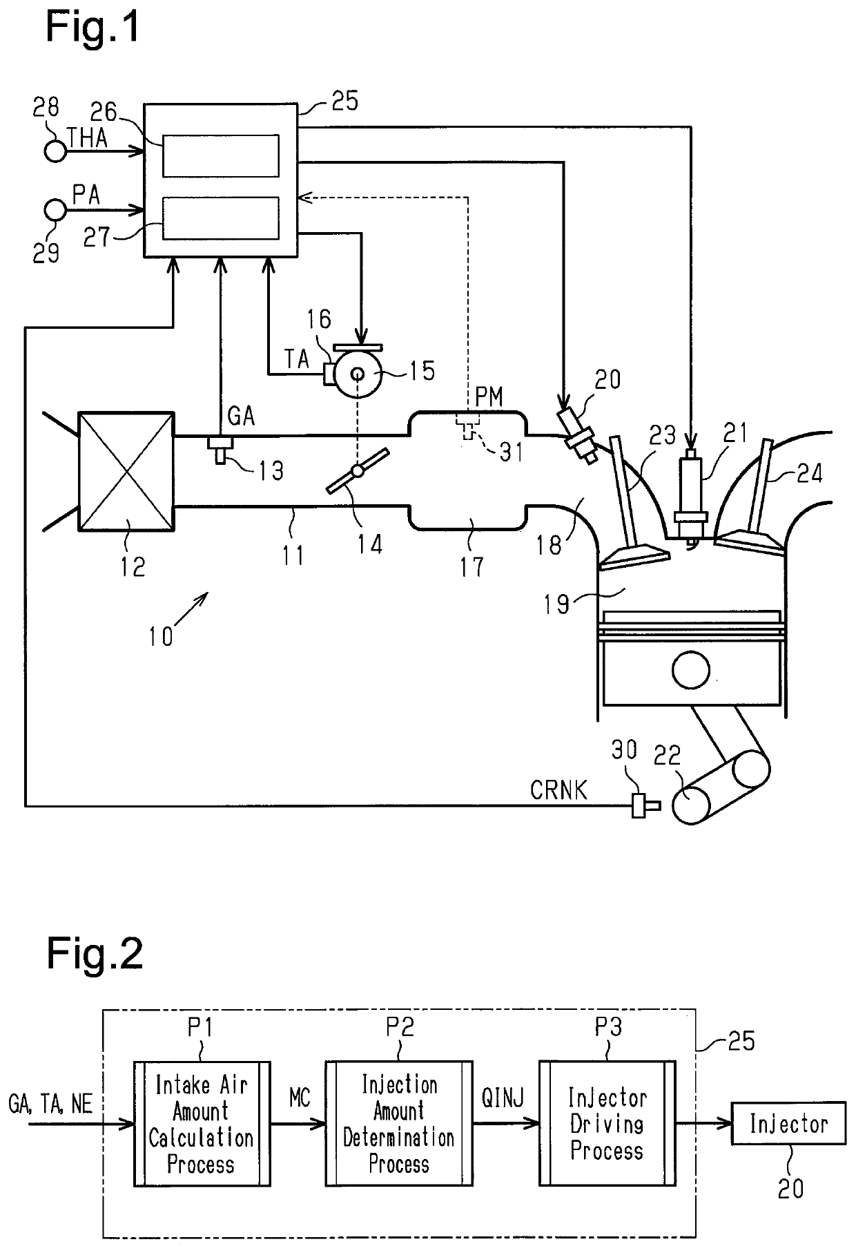
[0072]FIG. 1 shows an engine 10 for which the engine controller of the present embodiment is employed. The engine 10 includes an intake passage 11. An air cleaner 12 that filters dust or the like in intake air is arranged on the most upstream side of the intake passage 11. An air flowmeter 13 that detects an intake air flow rate is arranged in the portion of the intake passage 11 located downstream of the air cleaner 12. Further, a throttle valve 14 for adjusting the intake air flow rate of the intake passage 11 is arranged in the portion of the intake passage 11 located downstream of the air flowmeter 13. In the vicinity of the throttle valve 14, a throttle motor 15 and a throttle sensor 16 are arranged. The throttle motor 15 opens and closes the throttle valve 14, and the throttle sensor 16 detects the opening degree (throttle opening degree TA) of the throttle valve 14....

second embodiment

[0098]An engine controller according to a second embodiment will now be described also with reference to FIG. 7. In the present embodiment and each of the embodiments described later, like or same reference numerals are given to those components that are the same as the corresponding components of the above-described embodiment. Such components will not be described in detail.

[0099]In the structure of the engine 10 for which the engine controller of the present embodiment is employed, an intake pipe pressure sensor 31 shown by the broken line in FIG. 1 is added to the structure of the engine 10 of the first embodiment. The intake pipe pressure sensor 31 is arranged in the portion of the intake passage 11 located downstream of the throttle valve 14 (i.e., arranged in the intake manifold 17). The intake pipe pressure sensor 31 detects the pressure of intake air in this portion (hereinafter referred to as intake pipe pressure PM). The detection signals of the intake pipe pressure senso...

third embodiment

[0103]An engine controller according to a third embodiment will now be described also with reference to FIGS. 8 to 10.

[0104]In the engine controller of the present embodiment, an air model, which is a physical model of the intake system of the engine 10, is used to estimate the intake air amount. The air model is configured by sub-models including a throttle model M1, an intake pipe model M2, an intake valve model M3, and an air cleaner model M4.

[0105]The throttle model M1 is a physical model for the behavior of intake air in the throttle valve 14. More specifically, the throttle model M1 includes, as variables, a throttle upstream pressure PAC, the intake pipe pressure PM, an upstream temperature THAC, and the throttle opening degree TA. From the relationship of a constriction expression (1), the throttle model M1 calculates and outputs the flow rate of intake air passing through the throttle valve 14 (throttle passing intake air amount MT). The throttle upstream pressure PAC repre...


PUM


Abstract

A first intake air amount an engine is calculated based on a detected value of an intake air flow rate of an air flowmeter. A second intake air amount is calculated based on any one of a detected value of an intake pipe pressure and a throttle opening degree instead of the detected value of the intake air flow rate. When it is determined that the intake pulsation is not large, a difference amount of the second intake air amount from the first intake air amount is calculated. A corrected second intake air amount, which is a sum of the second intake air amount and the difference amount, is set as an intake air amount calculated value when it is determined that the intake pulsation is large.

Description

BACKGROUND1. Field[0001]The following description relates to an engine controller and an engine control method. In the engine controller and the engine control method, fuel injection control is performed for an injector by calculating the intake air amount of the engine and determining a fuel injection amount based on the calculated value of the intake air amount.2. Description of Related Art[0002]Proper control of the air-fuel ratio (mass ratio of fuel to air) of air-fuel mixture burned in cylinders requires accurate determination of the intake air amount of the engine, i.e., the mass of intake air flowing into the cylinders. Typical modes for calculating an intake air amount include three modes, namely, a mass flow mode, a speed density mode, and a throttle speed mode. In the mass flow mode, an air flowmeter is arranged in a portion of the intake passage located upstream of the throttle valve, and the intake air amount of the engine is calculated from the intake air flow rate dete...

Claims


Application Information

Patent Timeline
Patent Type & Authority Applications(United States)
IPC IPC(8): F02D41/24F02D41/30F02D13/02F02D41/00
CPCF02D41/2451F02D2200/101F02D2200/1002F02D41/2445F02D41/0002F02D41/2438F02D2200/0406F02D13/0234F02D2200/703F02D2041/001F02D41/0077F02D41/3005F02D41/18F02D41/3094F02D41/2429F02D41/0047F02D13/0203F02D41/182F02D2041/1433F02D2200/0404F02D2200/0402F02D2200/0414F02D2041/1413
Inventor YAMADA, TAKAFUMISHIBATA, HIROYUKIKURITA, SHUNSUKEANAMI, TAKAHIRO
Owner TOYOTA JIDOSHA KK
Why Eureka
Try Eureka