
Silicon carbide reinforced zirconium based cladding

a zirconium cladding and silicon carbide technology, applied in the direction of instruments, distance measurement, greenhouse gas reduction, etc., can solve the problems of forming in the spaces, expanding and bursting, and reducing the strength of the zirconium cladding metal protecting the nuclear fuel

Active Publication Date: 2020-01-16
WESTINGHOUSE ELECTRIC CORP
View PDF0 Cites 3 Cited by
  • Summary
  • Abstract
  • Description
  • Claims
  • Application Information

AI Technical Summary

Benefits of technology

The patent describes a way to make nuclear fuel cladding tubes that are stronger and less likely to burst under high temperatures. The method involves covering the tube with a yarn made from ceramic fibers and then adding a coating to stick the yarn to the tube. The first coating, made of Nb or Nb alloy, fills the gaps between the yarn and the tube. Optional additional coatings made of Cr or Cr alloy can be added for added strength. This method helps prevent the cladding tube from ballooning and bursting during operation and ensures the tube provides structural support for the nuclear fuel.

Problems solved by technology

Under severe conditions such as “beyond design basis” accidents, metal cladding can react exothermally with steam at over 1093° C. These zirconium cladding metals protecting the nuclear fuel may lose strength during “a loss of coolant” accident, where reactor temperatures can reach as high as 1204° C., and expand and burst due to internal fission gases within the fuel rod.
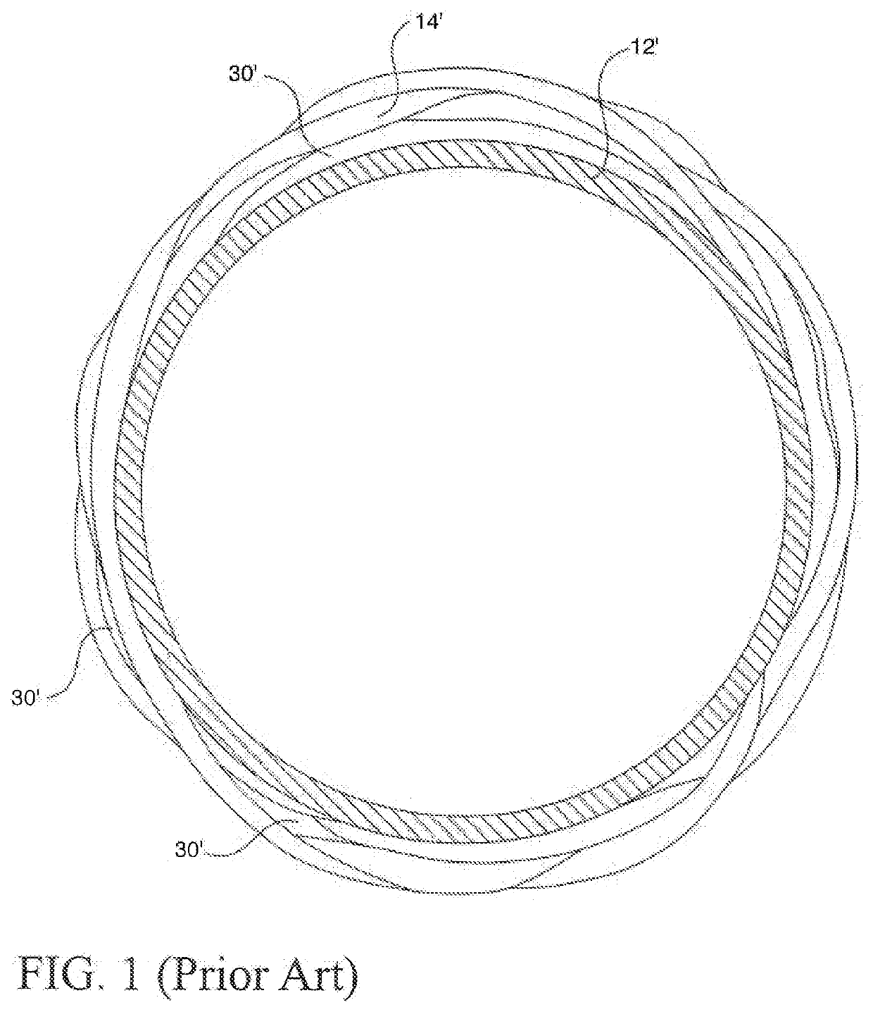
It was found that with this approach, there are gaps formed in the spaces between the exterior of the Zr cladding tube and the ceramic sleeve and further the ceramic winding can be damaged during removal of the mandrel.

Method used

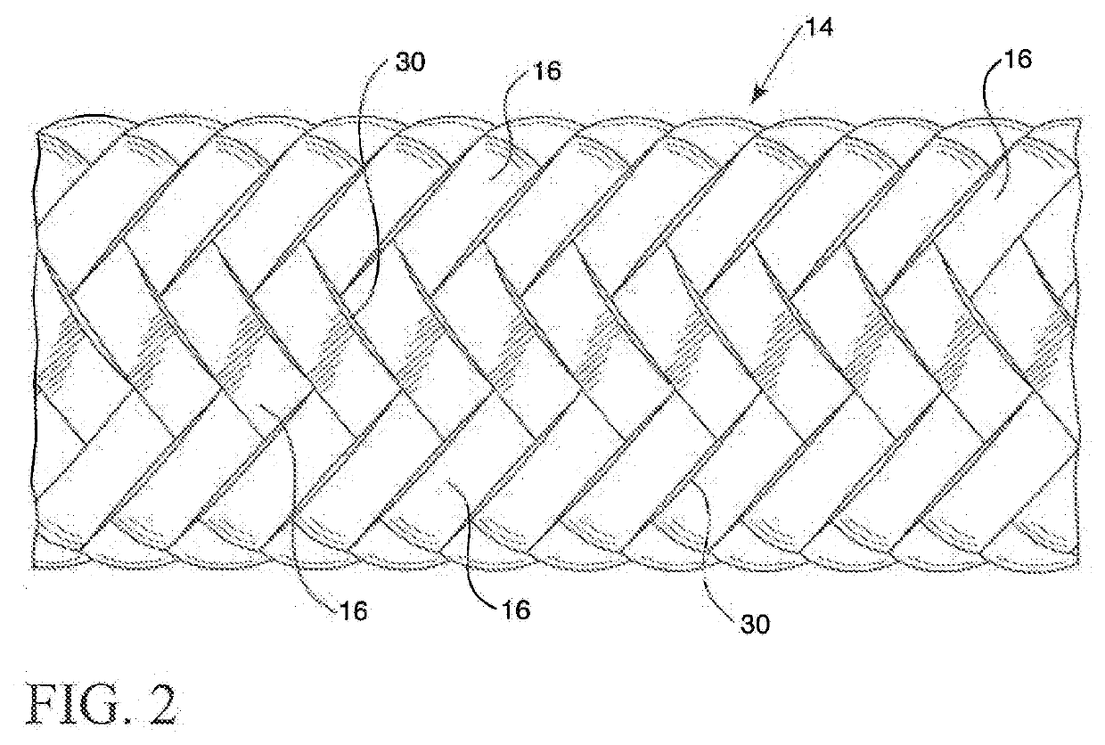
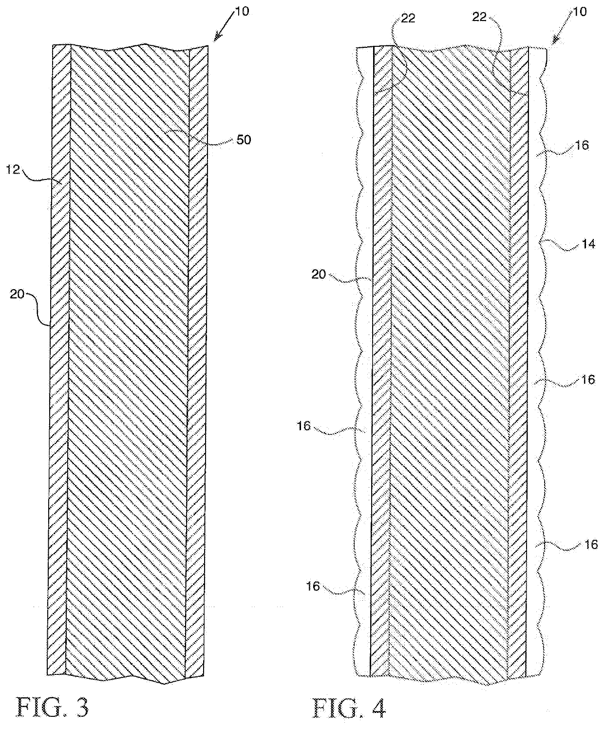

Image

  • Silicon carbide reinforced zirconium based cladding
  • Silicon carbide reinforced zirconium based cladding
  • Silicon carbide reinforced zirconium based cladding

Examples


Embodiment Construction

[0028]As used herein, the singular form of “a”, “an”, and “the” include the plural references unless the context clearly dictates otherwise.

[0029]Directional phrases used herein, such as, for example and without limitation, top, bottom, left, right, lower, upper, front, back, and variations thereof, shall relate to the orientation of the elements shown in the accompanying drawing and are not limiting upon the claims unless otherwise expressly stated.

[0030]In the present application, including the claims, other than where otherwise indicated, all numbers expressing quantities, values or characteristics are to be understood as being modified in all instances by the term “about.” Thus, numbers may be read as if preceded by the word “about” even though the term “about” may not expressly appear with the number. Accordingly, unless indicated to the contrary, any numerical parameters set forth in the following description may vary depending on the desired properties one seeks to obtain in ...


PUM

PropertyMeasurementUnit
thicknessaaaaaaaaaa
thicknessaaaaaaaaaa
temperaturesaaaaaaaaaa

Abstract

A method for making an improved nuclear fuel cladding tube includes reinforcing a Zr alloy tube by first winding or braiding ceramic yarn directly around the tube to form a ceramic covering, then physically bonding the ceramic covering to the tube by applying a first coating selected from the group consisting of Nb, Nb alloy, Nb oxide, Cr, Cr oxide, Cr alloy, or combinations thereof, by one of a thermal deposition process or a physical deposition process to provide structural support member for the Zr tube, and optionally applying a second coating and optionally applying a third coating by one of a thermal deposition process or a physical deposition process. If the tube softens at 800° C.-1000° C., the structural support tube will reinforce the Zr alloy tube against ballooning and bursting, thereby preventing the release of fission products to the reactor coolant.

Description

RELATED APPLICATIONS[0001]This application claims priority from U.S. Provisional Application Ser. No. 62 / 698,326 filed Jul. 16, 2018 and incorporated herein by reference.STATEMENT REGARDING GOVERNMENT RIGHTS[0002]This invention was made with government support under Contract No. DE-NE0008222 awarded by the Department of Energy. The U.S. Government has certain rights in this invention.BACKGROUND OF THE INVENTION1. Field of the Invention[0003]The present application relates to nuclear fuel claddings, and more particularly to zirconium alloy tubes with ceramic coatings.2. Description of the Prior Art[0004]In a typical nuclear reactor, the reactor core includes a large number of fuel assemblies, each of which is composed of a plurality of elongated fuel rods. The fuel rods each contain nuclear fuel fissile material, usually in the form of a stack of nuclear fuel pellets surrounded by a gas, such as He or H2. The fuel rods have a cladding that acts as a containment for the fissile materi...

Claims


Application Information

Patent Timeline
Patent Type & Authority Applications(United States)
IPC IPC(8): G21C3/07C23C14/18C23C14/08C23C24/04C23C4/06C23C4/11D04C1/06G21C3/04
CPCG21C3/07C23C4/11D04C1/06C23C4/06C23C14/18C23C24/04C23C14/083G21C3/047C23C24/08C23C4/02C23C4/18C23C4/134C23C24/085C23C24/087C23C4/131D04C1/02Y02E30/30
Inventor LAHODA, EDWARD J.
Owner WESTINGHOUSE ELECTRIC CORP
Learn More