
Aerodynamic surface of an aircraft

Inactive Publication Date: 2020-01-23
NIZOV SERGEI NIKOLAEVICH
View PDF0 Cites 1 Cited by
  • Summary
  • Abstract
  • Description
  • Claims
  • Application Information

AI Technical Summary

Benefits of technology

The invention relates to an aerodynamic surface for aircraft that reduces drag and increases lift-to-drag ratio at low angles of attack. The surface has a cambered airfoil section and teeth that deflect towards the smallest degree of curvature, which generates adjoining vortex cores and reduces drag. The leading edge of the surface can be made wavy, and the teeth are on the protrusions of the wavy surface, which further reduces drag. The aerodynamic surface also has a deflectable trailing edge assembly that allows for synchronous deflection and simultaneous aerodynamic compensation of the hinge moment of the assembly. The leading and trailing aerodynamic members can be designed to generate vortex cores and increase the margin angle-of-attack stability of the aircraft. The use of this aerodynamic surface also reduces the risk of injury and prevents engagement with branches and grass during take-offs and landings.

Problems solved by technology

A disadvantage of the known technical solution is, in particular, the impossibility to use a vortex-induced lift produced by the elevator teeth to increase a load-bearing capacity of the aerodynamic surfaces having a high aspect ratio.
Furthermore, the vortex cores adjoining the upper surface of the wing divide the longitudinally moving boundary layer on the upper surface of the wing into separate sections, which reduces the probability of migration of the lift-off areas of the boundary layer along the wingspan, which in turn increases the permissible roll angular rates at low airspeeds.
A disadvantage of this technical solution is its relatively narrow field of use limited to aircrafts having underwing engines.
The disadvantage of such technical solution is an increased Cx of the wing at low angles of attack during cruise flight modes, since the vortex generators disposed on the upper surface of the wing behind the leading edge thereof can not be “turned off” due to their streamwise disposition at angles of attack corresponding to the cruise airspeed.
This disadvantage partially eliminates the advantages in flight maneuverability and safety from the energy growth of the boundary layer at high angles of attack.
A disadvantage of this wing is the alternating-sign retrimming of the aircraft when an angle of attack is changed and at the same time the nonlinearity of the dependence of the aerodynamic center shift from the angle of attack is increased with an increase in the aerodynamic efficiency of the body strake, which is carried out by increasing the length thereof and sharpening the incoming edges, which requires application of high-speed fly-by-wire systems (FBWS) on the aircraft whose wing has a highly efficient and extended body strake.
Nevertheless, it should be noted that problems with “vortex” retrimming when an angle of attack is changed are characteristic of only multi-mode aircrafts with a wing having a low aspect ratio, the maximum chord of which along the body strake base, as a rule, exceeds a half of the total length of the aircraft, and the all-moveable horizontal empennage is disposed almost immediately adjacent to the trailing edge of the wing.
A disadvantage of this aerodynamic surface is a limited efficiency at high angles of attack, since the wavy leading edge, unlike the developed body strake of the wing, is not capable of forming sufficiently powerful vortices.
Furthermore, the manufacturing complexity should be noted, since the wavy shape is given to the entire aerodynamic surface.
A disadvantage of such technical solution is a limited field of its use.
A disadvantage of the known aerodynamic surface is a low level of lateral damping, which expressed itself in the roll oscillations characteristic of the MiG-23 MLD within a particular range of angles of attack, as well as the deterioration of the lift over drag ratio of the wing due to the local shock waves in the recesses at the tooth bases.
Furthermore, in the presence of a considerable roll angular rate and, correspondingly, an equally considerable difference in local angles of attack, the tooth groups generate diagonally disposed “damping” vortices, which tend to reduce the roll angular rate by applying suction to opposite wing surfaces.
Disadvantages of the known wing having teeth on the leading edge are the following:an increased drag due to the disposition of the edges of the vortex generator not streamwise at low positive angles of attack, which results in the impossibility to dispose the teeth along the entire length of the leading edge of the wing;deterioration of the lateral handling of the aircraft, in particular, as a result of the impossibility to achieve high roll angular rates due to the need to overcome the vortex damping moment by increasing the deflection angle or the flight control surface area, which makes it impossible to simultaneously improve the stall resistance and the aircraft sensitivity;an increased risk of injury when handling a known wing due to the presence of sharp teeth.

Method used


Image

  • Aerodynamic surface of an aircraft
  • Aerodynamic surface of an aircraft
  • Aerodynamic surface of an aircraft

Examples


first embodiment

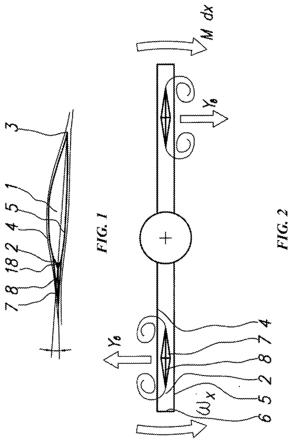
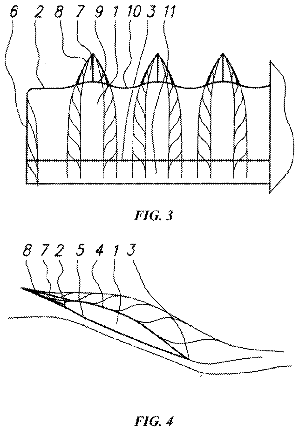
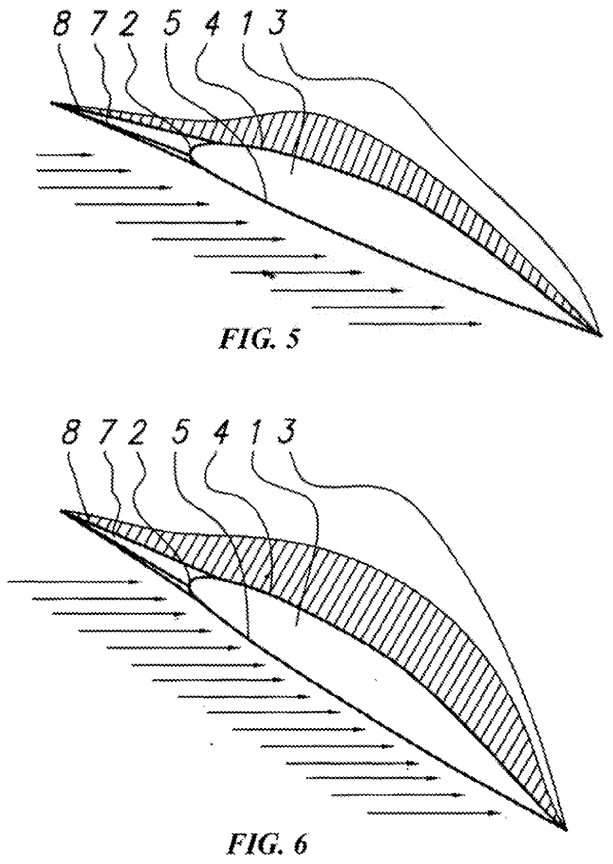
[0057]An aerodynamic surface of an aircraft according to the invention shown in FIG. 1 is made in the form of a console and comprises a main part 1 having a cambered airfoil section, and having a leading edge 2, a trailing edge 3, an upper side 4, a lower side 5 and a tip 6. Vortex generators made in the form of teeth 7 having edges 8 disposed along the length of the teeth 7 are arranged on the leading edge 2. The teeth 7 are deflected towards the smallest degree of curvature of the airfoil section of the main part 1.

[0058]It is also possible to make the main part 1 with a wavy leading edge 2 (FIG. 3), which includes cyclically repeating protrusions 9 and recesses 10, wherein the teeth 7 are disposed on the protrusions 9.

second embodiment

[0059]An aerodynamic surface of an aircraft according to the invention shown in FIG. 7 is characterized by a movable mounting of the tooth or teeth 7 and the presence of a deflectable trailing edge assembly 11, wherein the tooth 7 and the deflectable trailing edge assembly 11 are mounted on the main part 1 by means of hinges 12 and are provided with pylons 13. The pylons 13 mounted on the teeth 7 are kinematically connected to the pylons 13 of the deflectable trailing edge assembly 11 by means of at least one linkage 14, wherein the main part 1, the pylons 13 and the linkage 14 form a parallel-link motion.

third embodiment

[0060]An aerodynamic surface of an aircraft according to the invention is characterized by the implementation of the main part 1 in the form of a leading aerodynamic member 15 and a trailing aerodynamic member 16 disposed one after another. The teeth 7 are disposed in the gap between these aerodynamic members, forming trapezoidal windows 17 tapering in the flight direction. The side walls of the trapezoidal windows are the incoming edges 8.

[0061]The aerodynamic surface of the aircraft according to the first embodiment of the invention operates as follows.

[0062]At low positive angles of attack of the main part 1 of the aerodynamic surface 15, the teeth 7, due to their deflection towards the smallest degree of curvature of the airfoil section of the main part 1, are strictly streamwise and have a near-zero angle of attack (see FIG. 1), which reduces a drag and increases a lift over drag ratio, which is especially important with the laminar foil of the main part 1, the foil having a Cy...


PUM


Abstract

An aerodynamic surface of an aircraft comprises a main part having a leading and a trailing edges and having an airfoil section. The aerodynamic surface also having at least two vortex generators in the form of teeth having edges along the length thereof. The teeth are mounted on the leading edge of the main part so as to be capable of generating two vortex cores on one tooth. The edges of a tooth adjoin the leading edge of the main part of the aerodynamic surface. The radius of an edge of each tooth along the length of the vortex generator is five times less than the radius of the leading edge of the main part. The main part of the aerodynamic surface has a cambered airfoil section, wherein the teeth are mounted with a deflection towards the smallest degree of curvature of the airfoil section of the main part. The invention is intended for reducing an aerodynamic drag at low angles of attack while maintaining an increased load hearing capacity of the aerodynamic surface by generating vortex cores adjoining one of the sides thereof.

Description

FIELD OF THE INVENTION[0001]The invention relates to aircraft engineering, in particular to various aircrafts using fixed, moveable, rotating and flapping aerodynamic surfaces for creating aerodynamic forces and moments.BACKGROUND OF THE INVENTION[0002]A horizontal empennage of a radio-controlled aerobatic model of the Ultimate AMR aircraft is known, produced by the Australian Precision Aerobatics company, photographs of which are available on the Internet at https: / / www.precisionaerobatics.com / productiultimate-amr / .[0003]An aerodynamic surface of this model is made with at least two wedge-shaped teeth, each tooth having at least one sharpened incoming edge and mounted so as to be capable of generating vortex cores on the low-pressure side with an asymmetric flow around the aerodynamic surface. In fact, such aerodynamic surface is one of the options for implementing the horn balance of the elevator, in which the elevator part disposed in front of the elevator hinge fitting axis is m...

Claims


Application Information

Patent Timeline
Patent Type & Authority Applications(United States)
IPC IPC(8): B64C23/06B64C3/14
CPCB64C2230/04B64C23/069B64C3/14B64C21/10B64C23/06B64C2003/146Y02T50/10
Inventor NIZOV, SERGEI NIKOLAEVICH
Owner NIZOV SERGEI NIKOLAEVICH
Learn More