
Fuel assembly

a technology of fuel assembly and fuel, which is applied in the direction of reactor fuel susbtance, nuclear elements, greenhouse gas reduction, etc., can solve the problems of high average energy of fuel assembly, difficult energy spectrum of neutrons, enrichment procedures, etc., to improve the shutdown margin of nuclear reactors, enhance the value of burnable poison, and facilitate the effect of neutron moderation

Active Publication Date: 2020-01-23
HITACHI-GE NUCLEAR ENERGY LTD
View PDF0 Cites 0 Cited by
  • Summary
  • Abstract
  • Description
  • Claims
  • Application Information

AI Technical Summary

Benefits of technology

The invention is a fuel assembly for a nuclear reactor that improves safety during shutdowns. By adding two third fuel rods and a second fuel rod adjacent to the third fuel rod, the void fraction in the coolant region is reduced, leading to better moderation of neutrons and increased safety during shutdowns. The value of the burnable poison in the fuel rod is increased, making it more efficient in shutting down the reactor.

Problems solved by technology

However, the reactor core loaded with the MOX fuel assembly has a high average energy of the neutrons (the energy spectrum of the neutrons becomes hard).
In addition, since the uranium is taken out by the reprocessing, there is no enrichment procedure to increase a plutonium enrichment unlike the uranium fuel.
Therefore, the MOX fuel assembly is hindered from being enriched.
An additive amount of the burnable poison in the nuclear fuel material in the fuel rod is limited by a manufacturing performance of the fuel rod containing the burnable poison and a reduction in the thermal conductivity of the fuel rod containing the burnable poison.

Method used


Image

  • Fuel assembly
  • Fuel assembly
  • Fuel assembly

Examples


first embodiment

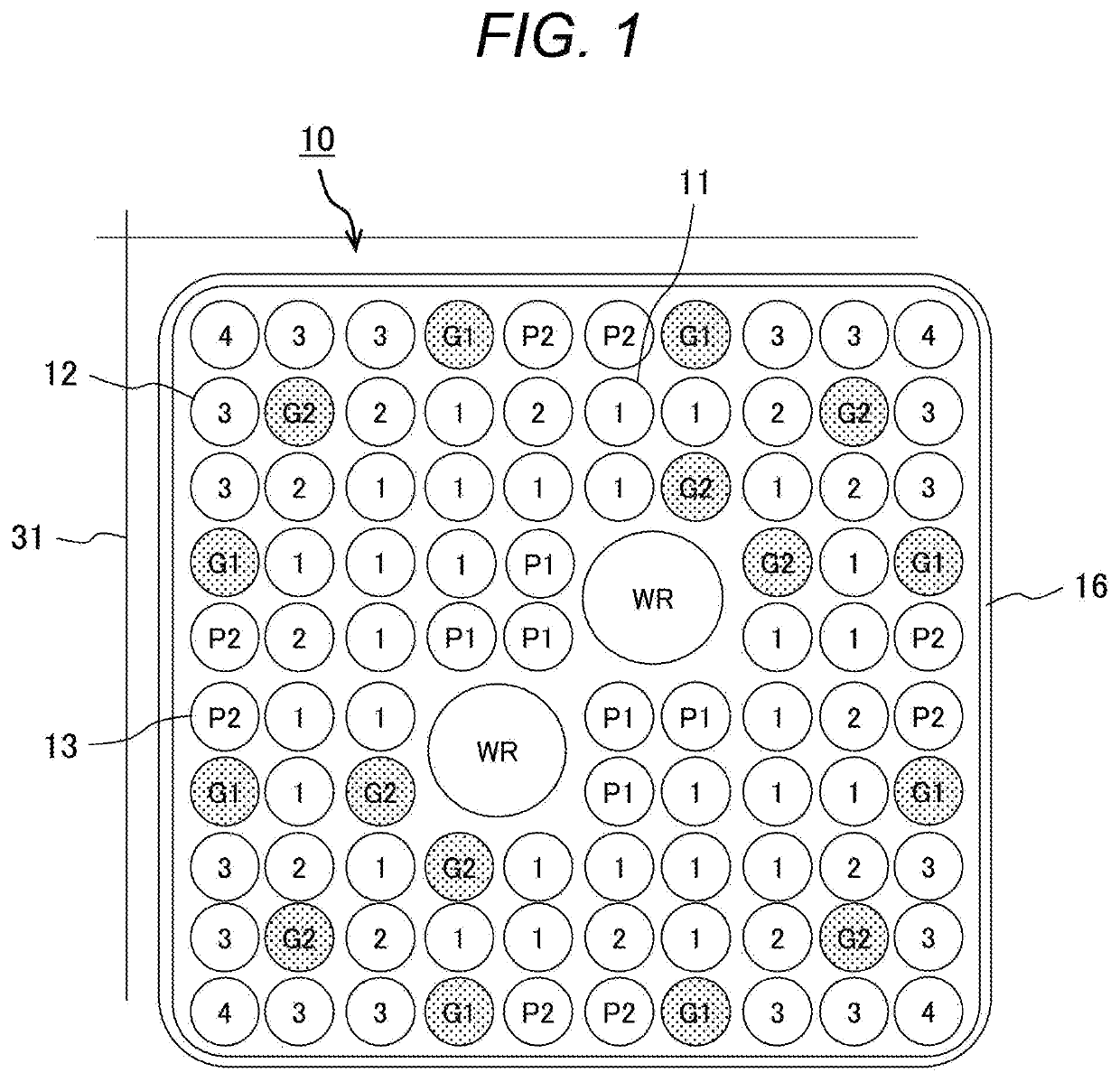
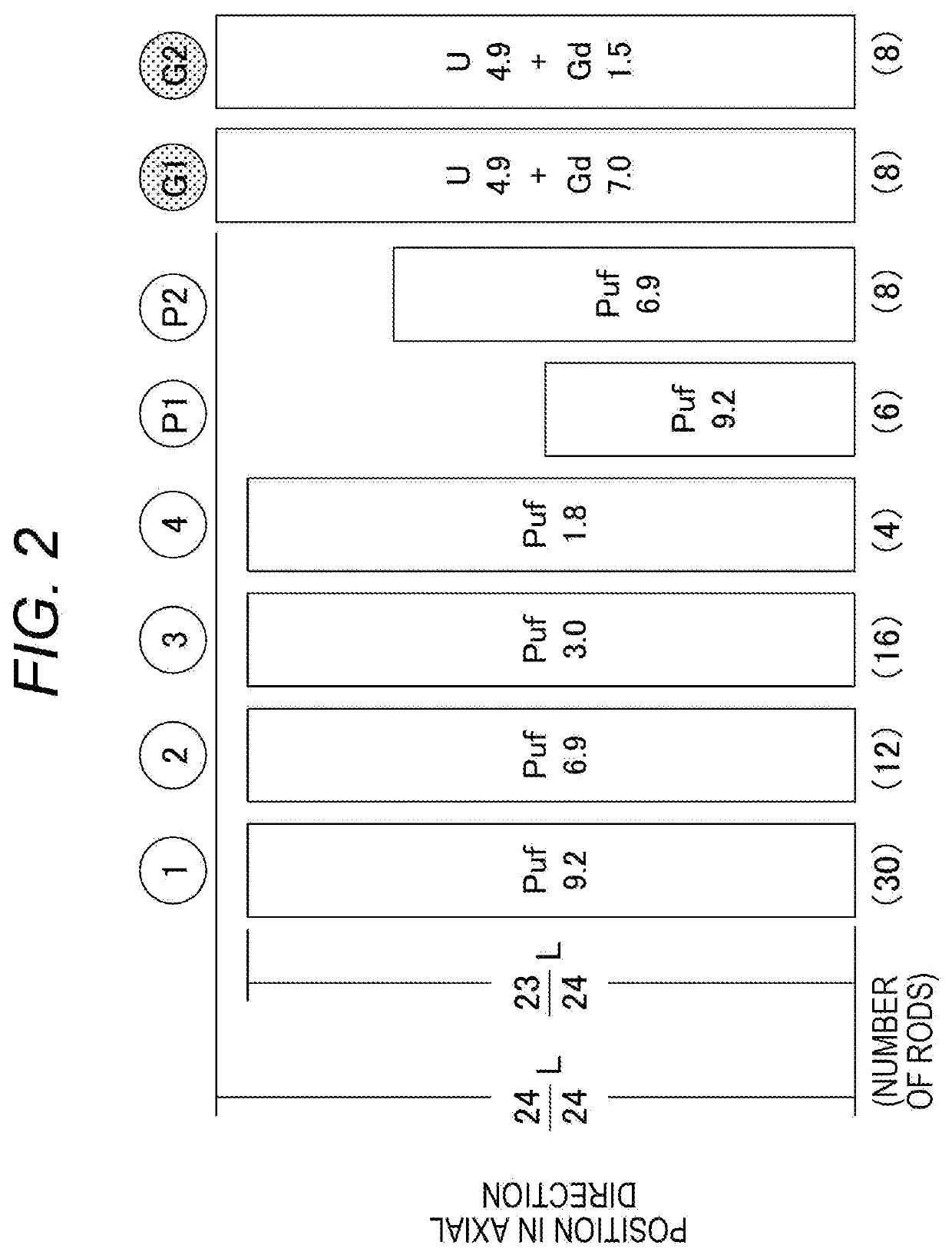
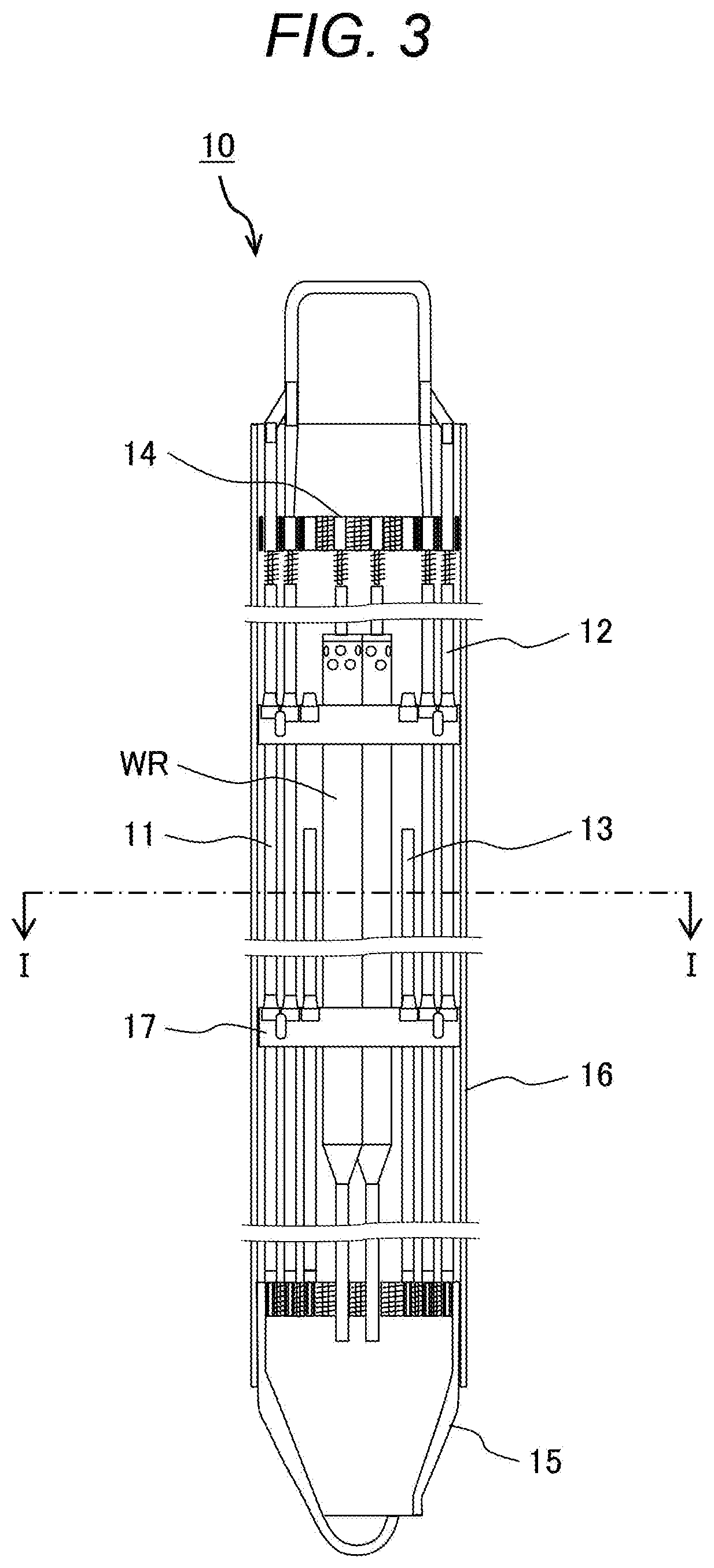
[0050]A fuel assembly of a first embodiment applied to the advanced boiling-water nuclear power plant which is a preferred embodiment of the invention will be described using FIGS. 1, 2, and 3.

[0051]Before starting the description of the fuel assembly of this embodiment, the structure of the nuclear reactor of the advanced boiling-water nuclear power plant (ABWR plant) to which the fuel assembly is applied will be schematically illustrated on the basis of FIG. 4. The nuclear reactor 20 includes a reactor pressure vessel 21. The reactor core 23 loaded with a plurality of fuel assemblies (not illustrated) is disposed in the reactor pressure vessel 21. In the reactor pressure vessel 21, a cylindrical core shroud 22 surrounds the reactor core 23. A separator 24 disposed on the upper side of the reactor core 23 is disposed at the upper end of the core shroud 22. Further, a steam dryer 25 is disposed on the upper side of the separator 24 to be provided in the inner surface of the reactor ...

second embodiment

[0076]A fuel assembly of a second embodiment applied to the ABWR plant which is another preferred embodiment of the invention will be described using FIGS. 9 and 10.

[0077]A fuel assembly 10A of this embodiment is configured such that one full length fuel rod G2 in two full length fuel rods G2 disposed to be adjacent to each of two water rods WR of the fuel assembly 10 of the first embodiment is disposed to be adjacent to three partial length fuel rods P2 of the partial length fuel rod group in each of two partial length fuel rod groups adjacent to two water rods WR. In each of the two partial length fuel rod groups of the fuel assembly 10, the full length fuel rod 1 disposed to be adjacent to three partial length fuel rods P2 is disposed to be adjacent to the water rod WR. In other words, in the fuel assembly 10A, the full length fuel rods G2 adjacent to the water rod WR is less than the fuel assembly 10 by one, and the full length fuel rods 1 is more by one. One full length fuel ro...

third embodiment

[0080]A fuel assembly of a third embodiment applied to the ABWR plant which is another preferred embodiment of the invention will be described using FIGS. 11 and 12.

[0081]A fuel assembly 10B of this embodiment is configured to include four partial length fuel rods GP instead of four partial length fuel rods P1 used in the fuel assembly 10 of the first embodiment, and the full length fuel rods G2 is reduced by four from the fuel assembly 10. In the fuel assembly 10B, four full length fuel rods G2 are disposed at four corners of the fuel rod layout of the second row from the inner surface of the channel box 16. The partial length fuel rod GP contains the nuclear fuel material and the burnable poison. The nuclear fuel material in the partial length fuel rod GP does not contain plutonium, but contains fissile uranium (for example, U-235) and a non-fissile uranium (for example, U-238). In the partial length fuel rod GP, the uranium enrichment is 4.9 wt %, and the concentration of gadolin...


PUM


Abstract

A fuel assembly includes full length fuel rods which contain a plutonium fissile (Puf) but do not contain a burnable poison, full length fuel rods which contain the fissile uranium and the burnable poison, and partial length fuel rods which contain Puf but do not contain the burnable poison in a channel box. The plutonium enrichment is decreased in an order of the full length fuel rods. The concentration of the burnable poison of the full length fuel rod is higher than the concentration of the full length fuel rod. In each side of a rectangular outermost periphery adjacent to the inner surface of the channel box in a horizontal cross-sectional view of the fuel assembly, two partial length fuel rods are adjacently disposed, and the full length fuel rod containing the burnable poison is disposed to be adjacent to each partial length fuel rod.

Description

CLAIM OF PRIORITY[0001]The present application claims priority from Japanese Patent application serial No. 2018-066985, filed on Mar. 30, 2018, the content of which is hereby incorporated by reference into this application.BACKGROUND OF THE INVENTION1. Field of the Invention[0002]The invention relates to a fuel assembly, and particularly to a fuel assembly which is suitable to a boiling-water reactor.2. Description of the Related Art[0003]In a reactor core of a boiling-water reactor, a plurality of fuel assemblies is loaded. The fuel assembly includes a plurality of fuel rods where a plurality of fuel pellets containing a nuclear fuel material (for example, uranium oxide) is sealed, an upper tie plate (upper fuel support member) which supports the upper end of the fuel rod, a lower tie plate (lower fuel support member) which supports the lower end of the fuel rod, a plurality of fuel spacers which holds a gap between the fuel rods, a water rod, and a square channel box of which the ...

Claims


Application Information

Patent Timeline
Patent Type & Authority Applications(United States)
IPC IPC(8): G21C3/326G21C3/26G21C3/33G21C3/58G21C3/34G21C3/332
CPCG21C3/34G21C3/332G21C3/3315G21C3/26G21C3/3305G21C3/58G21C3/326G21C3/328Y02E30/30
Inventor MITSUYASU, TAKESHIAOYAMA, MOTOO
Owner HITACHI-GE NUCLEAR ENERGY LTD
Learn More