Gas intensifier with lubrication

a technology of gas intensifier and lubricating layer, which is applied in the direction of engine lubrication, liquid fuel engine, mechanical apparatus, etc., can solve the problems of increasing the temperature of the equipment, high maintenance cost and low durability of commonly used compression equipment, and the most costly step of compression. , to achieve the effect of prolonging the operating li

Inactive Publication Date: 2020-02-06
METENER OY
View PDF0 Cites 27 Cited by
  • Summary
  • Abstract
  • Description
  • Claims
  • Application Information

AI Technical Summary

Benefits of technology

[0004]The objective is to present an intensifier with a lubrication system that will in addition provide cooling, which will at least redu

Problems solved by technology

Compression is often the most costly step in biogas treatment, as commonly used compression equipment has high maintenance expenses and low durability.
Drawbacks of using e.g. existing hydraulic compressors for elevating the pressure of the target

Method used


Image

  • Gas intensifier with lubrication
  • Gas intensifier with lubrication

Examples


Embodiment Construction

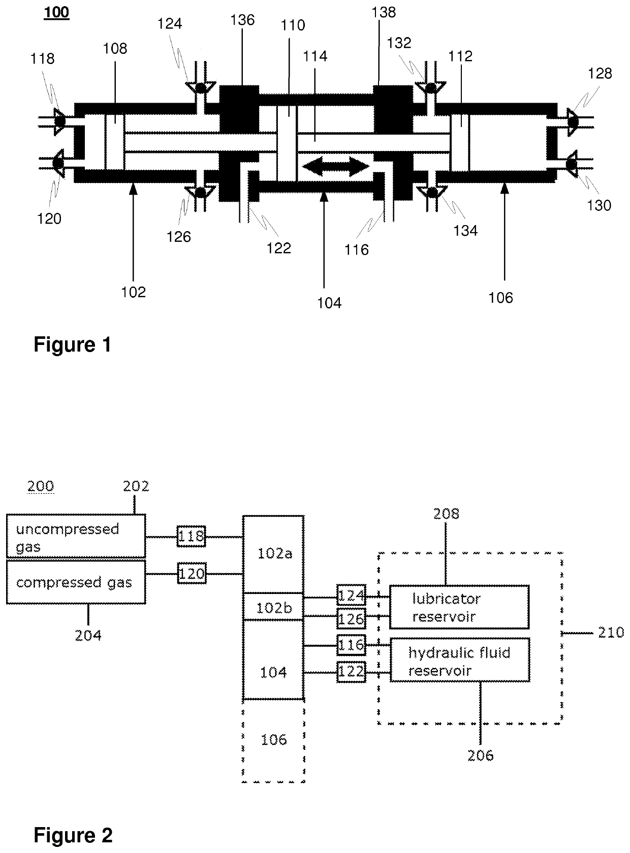
[0013]FIG. 1 depicts one embodiment of a compressor device preferably in the form of an intensifier, or “booster”, according to the present invention intended for increasing the pressure of a gas. That is, compression of gas using a compressor arrangement is the matter that is discussed. In some embodiments, the gas that the intensifier, or compressor, may be used to increase the pressure of may include biogas or natural gas.

[0014]The term “intensifier unit” refers hereafter to an intensifier device which comprises one (common) body of preferably rigid type. In some embodiments, the body may be of substantially monolithic nature defined by a single element or several permanently attached elements. In some other embodiments the body may comprise multiple functional elements such as chambers removably connected together by necessary fixing elements such as bolts.

[0015]In the shown embodiment, a single-stage double-acting intensifier unit is presented, but the fundamental principle of ...


PUM


Abstract

A hydraulically driven intensifier for increasing pressure of gas comprising a piston-driven compression chamber for gas, operatively connected to an adjacent hydraulic chamber, with lubricant coupling in the compression chamber of the intensifier to circulate the lubricating fluid for cooling and lubricating the piston. A multistage compression system for gas, comprising the aforementioned intensifier, preferably several thereof operatively connected in series.

Description

FIELD OF THE INVENTION[0001]The present invention is related to increasing the pressure of gas. Particularly, but not by way of limitation, a hydraulically driven positive displacement gas intensifier with provision of a lubrication system is presented.BACKGROUND OF THE INVENTION[0002]After or in connection with purification of raw biogas to obtain biomethane, the gas is at least temporarily stored in compressed form. Compression is often the most costly step in biogas treatment, as commonly used compression equipment has high maintenance expenses and low durability.[0003]Drawbacks of using e.g. existing hydraulic compressors for elevating the pressure of the target gas, such as the aforementioned biogas, include wearing of parts due to friction, a rise in temperature of the equipment, and formation of soot, which lead to a shortening of the operating life of the compressor among other potential side effects.SUMMARY OF THE INVENTION[0004]The objective is to present an intensifier wi...

Claims


Application Information

Patent Timeline
IPC IPC(8): F04B39/02F16N21/00F16N7/38F04B27/00F04B27/02F15B3/00
CPCF16N21/00F16N2210/16F04B39/02F15B3/00F16N7/38F04B27/005F04B27/02F04B9/113F04B25/00F04B35/00F04B41/06F04B53/18F04B9/10F04B39/00F16N13/02
Inventor KALMARI, ERKKIKALMARI, JOHANNALUOSTARINEN, JUHA
Owner METENER OY
Why Eureka
Try Eureka