
Gradient system with controlled cooling in the individual gradient channels

a cooling system and gradient coil technology, applied in the field of scanning imaging systems, can solve problems such as reducing flow resistan

Active Publication Date: 2020-02-13
KONINKLJIJKE PHILIPS NV
View PDF0 Cites 3 Cited by
  • Summary
  • Abstract
  • Description
  • Claims
  • Application Information

AI Technical Summary

Benefits of technology

The present system and method improve the cooling efficiency of a magnetic resonance imaging (MRI) machine by controlling the flow rates of the coolant through the gradient coils using flow control devices. This allows for better image quality and faster acquisitions. Additionally, the system can split the coolant flow into parallel streams based on how the gradient coils are actually used, preventing the heating of the gradient coils in advance. This embodiment also allows for continuous monitoring of the heat load for timely reaction to unexpected increases. The coolant tubes are hollow conductors of the gradient coils or coolant pipes in contact with the gradient coils, providing a compact design of the gradient coil system.

Problems solved by technology

Having multiple tubes in parallel may reduce flow resistance e.g. for cooling water.

Method used


Image

  • Gradient system with controlled cooling in the individual gradient channels
  • Gradient system with controlled cooling in the individual gradient channels
  • Gradient system with controlled cooling in the individual gradient channels

Examples


Embodiment Construction

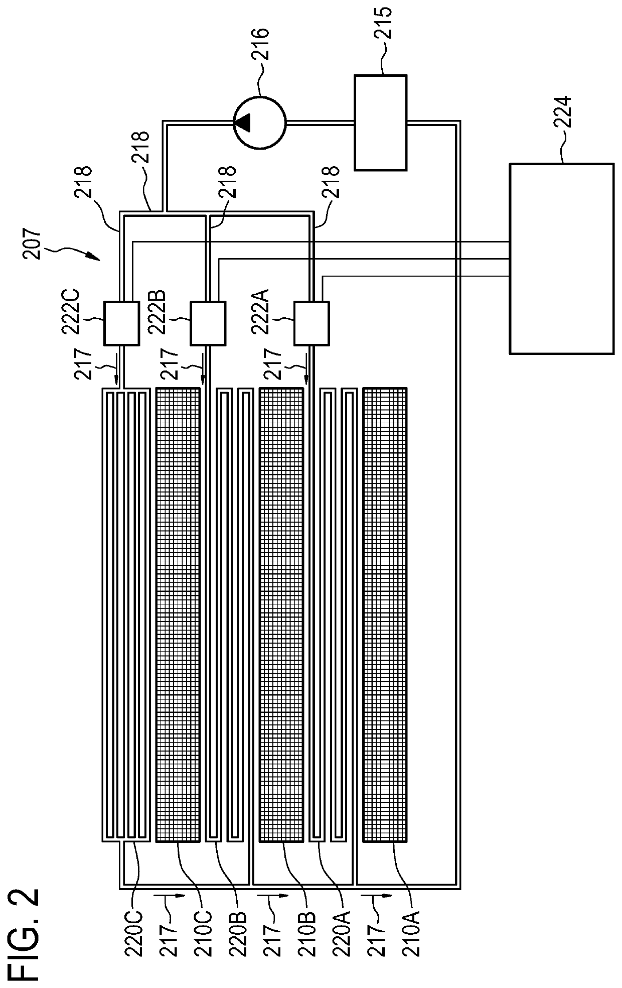
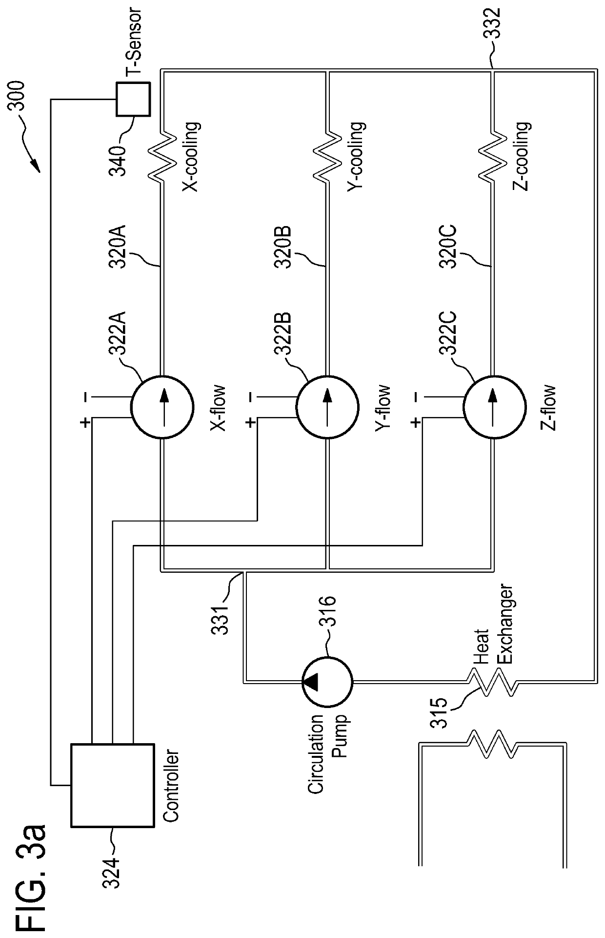
[0036]In the following, like numbered elements in the figures are either similar elements or perform an equivalent function. Elements which have been discussed previously will not necessarily be discussed in later figures if the function is equivalent.

[0037]Various structures, systems and devices are schematically depicted in the figures for purposes of explanation only and so as to not obscure the present invention with details that are well known to those skilled in the art. Nevertheless, the attached figures are included to describe and explain illustrative examples of the disclosed subject matter.

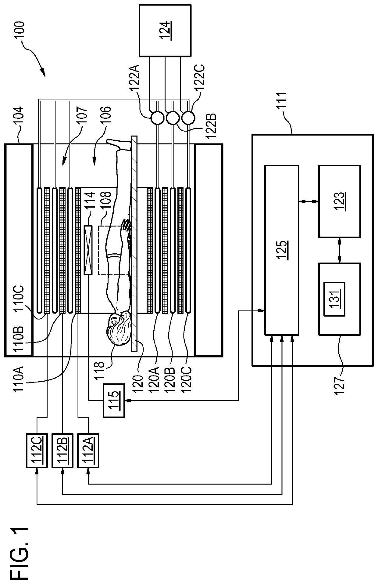
[0038]FIG. 1 illustrates a magnetic resonance imaging system 100 as an example of the medical system 100. The magnetic resonance imaging system 100 comprises a magnet 104. The magnet 104 is a superconducting cylindrical type magnet with a bore 106 in it. The use of different types of magnets is also possible; for instance, it is also possible to use both a split cylindrical magnet and a...


PUM

PropertyMeasurementUnit
coil resistancesaaaaaaaaaa
flow ratesaaaaaaaaaa

Abstract

The present disclosure relates to a gradient coil system (107, 207) for a magnetic resonance imaging, MRI, system (100). The gradient coil system (107, 207) comprises: a plurality of gradient coils (110A-C, 210A-C) for applying a gradient magnetic field to a target volume (108); at least one coolant tube (120A-C, 220A-C, 320A-C) per gradient coil (110A-C, 210A-C) for cooling the gradient coil (110A-C, 210A-C), the coolant tubes (120A-C, 220A-C, 320A-C) being connected to respective flow control devices (122A-C, 222A-C, 322A-C); a controller (124, 224, 324) coupled to the coolant tubes (120A-C, 220A-C, 320A-C) configured to control each flow control device of the flow control devices (122A-C, 222A-C, 322A-C) for adjusting the flow of a coolant in the respective coolant tube (120A-C, 220A-C, 320A-C), wherein the controller (124, 224, 324) is configured to control the flow control device (122A-C, 222A-C, 322A-C) on the basis of heat load caused by the respective gradient coil (110A-C, 210A-C).

Description

FIELD OF THE INVENTION[0001]The invention relates to scanning imaging systems, in particular to a cooling system for a gradient coil apparatus.BACKGROUND OF THE INVENTION[0002]A chiller utilizing water or a water and ethylene glycol mixture is typically used for removing heat from gradient coils of magnetic resonance (MR) systems. In order to minimize the flow impedance, the cooling systems consist of a number of parallel circuits served by the chiller. However, the gradient coils are not usually used at the same duty cycle and much of the capacity of the cooling system is wasted.[0003]The Japanese patent application JP H06-54819 relates to an open-type magnet with opposing pole pieces of a permanent magnet. Gradient coils are mounted to the respective pole pieces. These gradient coils are liquid cooled and the cooling for x-gradient coil and they-gradient coil of the same pole pieces are circuited in series. Cooling of the gradient (x,y) coils at different pole pieces is controlled...

Claims


Application Information

Patent Timeline
Patent Type & Authority Applications(United States)
IPC IPC(8): G01R33/385G01R33/54G01R33/56
CPCG01R33/543G01R33/3858G01R33/3856G01R33/56G01R33/546
Inventor OVERWEG, JOHANNES ADRIANUS
Owner KONINKLJIJKE PHILIPS NV
Learn More