Temperature sensor assembly for an electrical connector

Active Publication Date: 2020-02-27
TYCO ELECTRONICS LOGISTICS AG (CH)
View PDF4 Cites 11 Cited by
  • Summary
  • Abstract
  • Description
  • Claims
  • Application Information

AI Technical Summary

Benefits of technology

[0006]In one embodiment, an electrical connector is provided. The electrical connector includes a housing extending between a front and a rear. The housing has a chamber at the rear and a terminal channel between the front and the rear. The electrical connector includes a power terminal coupled to the housing. The power terminal includes a mating pin at a front of the power terminal and a cable connector at a rear of the power terminal. The mating pin is positioned in the terminal channel for mating with a charging connector. The cable connector is positioned in the chamber at the rear of the housing. The electrical connector includes a temperature sensor assembly positioned in the chamber. The temperature sensor assembly includes a sealing pad holding the power terminal. The temperature sensor assembly includes a thermal shunt held by the sealing pad. The temperature sensor assembly includes a temperature sensor coupled to the thermal shunt. The sealing pad has a terminal opening receiving the power terminal. The sealing pad is electrically insulative. The sealing pad is thermally coupled to the power terminal and thermally coupled to the thermal shunt. The sealing pad has a first thermal conductivity. The thermal shunt has a second thermal conductivity higher than the first thermal conductivity. The temperature sensor monitors the temperature of the power terminal through a thermal path defined by the sealing pad and the thermal shunt.
[0007]In another embodiment, a temperature sensor assembly for monitoring a temperature of a power terminal is provided. The temperature sensor assembly includes a sealing pad having a front and a rear. The sealing pad has a terminal opening therethrough receiving the power terminal such that a mating pin of the power terminal extends forward of the sealing pad for mating with a charging connector and a cable connector of the power terminal extends rearward of the sealing pad for terminal to a power cable. The sealing pad is an elastomer being electrically insulative and thermally conductive having a first thermal conductivity. The sealing pad is thermally coupled to the power terminal. The temperature sensor assembly includes a thermal shunt separate and discrete from the sealing pad. The thermal shunt is held by the sealing pad and extends rear

Problems solved by technology

However, at higher currents, the terminals and the power cables experience an increase in temperature, which may damage the components of the charging inlet assembly.
The thermal

Method used


Image

  • Temperature sensor assembly for an electrical connector
  • Temperature sensor assembly for an electrical connector
  • Temperature sensor assembly for an electrical connector

Examples


Embodiment Construction

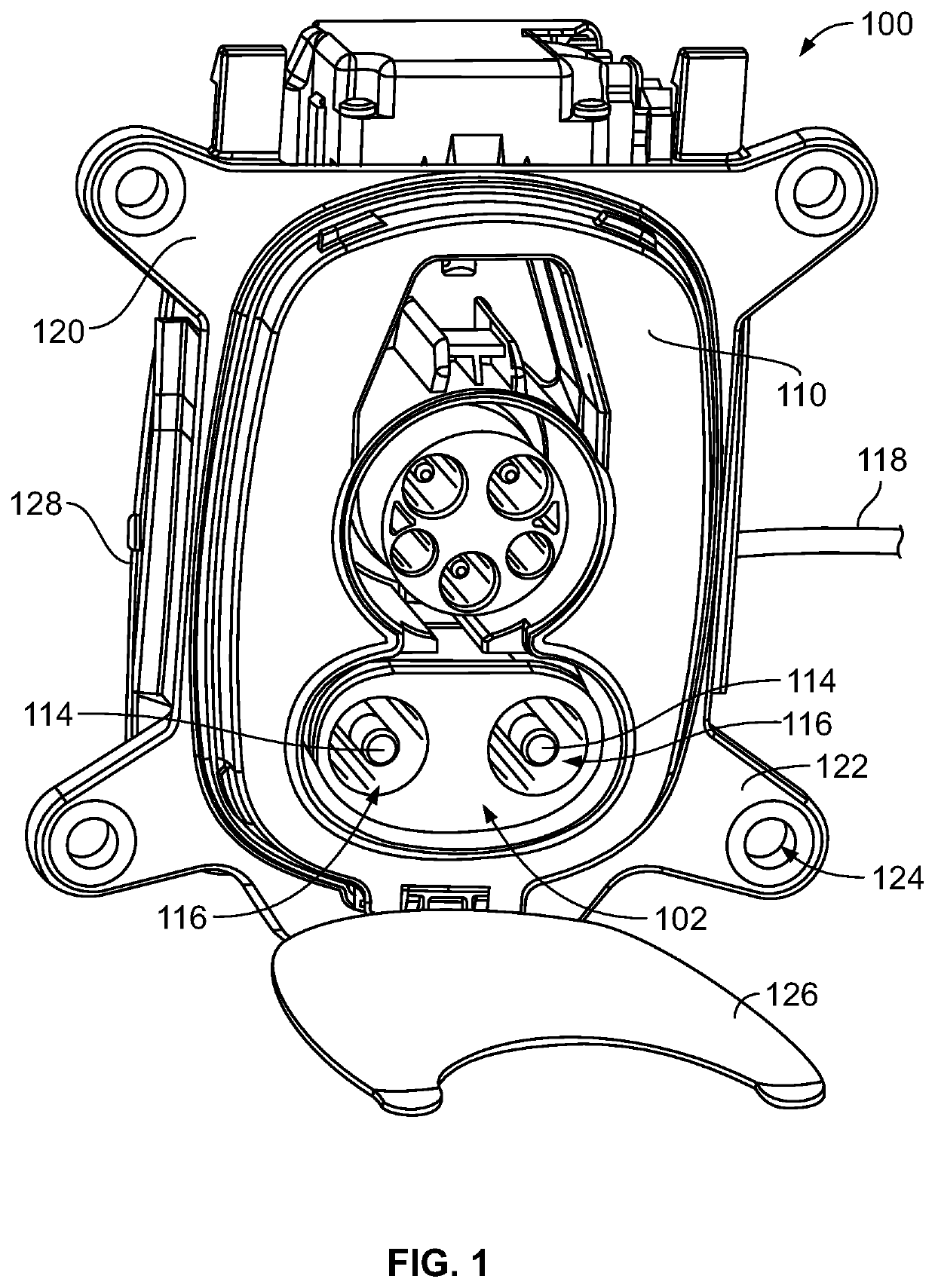
[0022]FIG. 1 is a front perspective view of a charging inlet assembly 100 including an electrical connector 102 in accordance with an exemplary embodiment. While the electrical connector 102 may be described herein as part of the charging inlet assembly, it is realized that the electrical connector 102 may be another type of electrical connector. The charging inlet assembly 100 is used as a charging inlet for a vehicle, such as an electric vehicle (EV) or hybrid electric vehicle (HEV). The electrical connector 102 of the charging inlet assembly 100 is configured for mating reception with a charging connector (not shown). In an exemplary embodiment, the electrical connector 102 is configured for mating with a DC fast charging connector, such as the SAE combo CCS charging connector, in addition to AC charging connectors, such as the SAE J1772 charging connector.

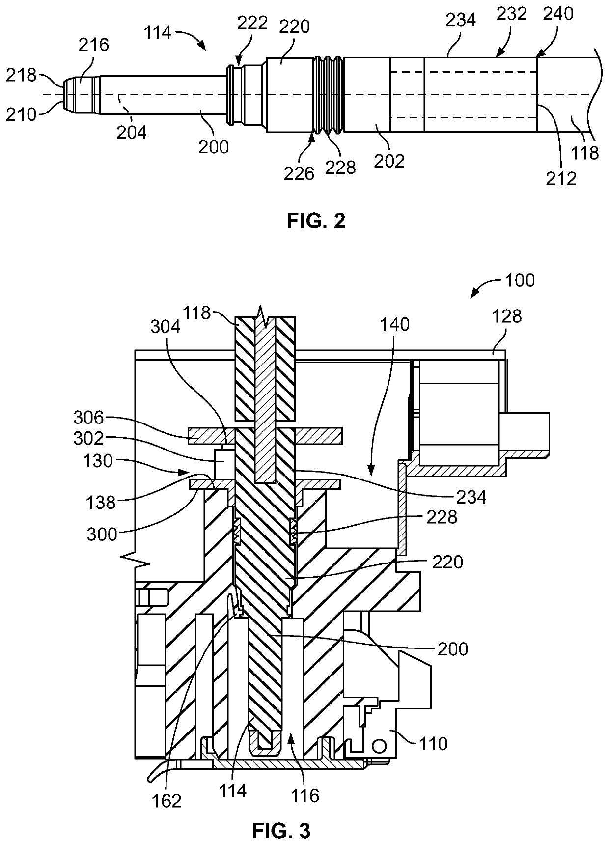
[0023]The electrical connector 102 of the charging inlet assembly 100 includes a housing 110 holding power terminals 114 form...


PUM


Abstract

An electrical connector including a housing having a terminal channel with a power terminal in the terminal channel. The electrical connector includes a temperature sensor assembly positioned in the chamber. The temperature sensor assembly includes a sealing pad holding the power terminal and a thermal shunt held by the sealing pad. A temperature sensor is coupled to the thermal shunt. The sealing pad is electrically insulative and has a terminal opening receiving the power terminal. The sealing pad is thermally coupled to the power terminal and thermally coupled to the thermal shunt. The thermal shunt has a thermal conductivity higher than a thermal conductivity of the sealing pad. The temperature sensor monitors the temperature of the power terminal through a thermal path defined by the sealing pad and the thermal shunt.

Description

CROSS REFERENCE TO RELATED APPLICATIONS[0001]This application claims benefit to U.S. Provisional Application No. 62 / 720,501, filed Aug. 21, 2018, titled “REDUCED SENSOR TIME CONSTANT FOR HEMS CONNECTORS”, the subject matter of which is herein incorporated by reference in its entirety.BACKGROUND OF THE INVENTION[0002]The subject matter herein relates generally to temperature sensor assemblies for electrical connectors.[0003]Electrical connectors, such as power connectors, generate heat when current flows through the terminals and cables of the power connectors. For example, an electrical connector of a charging inlet assembly for a battery system of an electric vehicle (EV) or hybrid electric vehicle (HEV) may generate heat through the terminals and the cables of the charging inlet assembly during a charging process. A charging connector is configured to be mated with the terminals of the charging inlet assembly to charge the battery system of the vehicle. It is desirable to increase...

Claims


Application Information

Patent Timeline
IPC IPC(8): H01R13/66G01K7/42
CPCH01R13/6683G01K7/42B60L53/16H01R13/7137G01K1/18H01R2201/26Y02T10/70Y02T10/7072Y02T90/14Y10S439/913
Inventor SARRAF, DAVID BRUCEMYER, NATHAN PHILIP
Owner TYCO ELECTRONICS LOGISTICS AG (CH)
Why Eureka
Try Eureka