Exoskeleton, orthosis, wearable device or mobile robots using magnetorheological fluid clutch apparatus

a technology of magnetorheological fluid clutch and exoskeleton, which is applied in the field of exoskeletons or orthoses/orthotics, can solve the problems of inconvenience for users, disruption of device function, and relatively low mechanical bandwidth of actuator types

Pending Publication Date: 2020-03-05
EXONETIK INC
View PDF9 Cites 13 Cited by
  • Summary
  • Abstract
  • Description
  • Claims
  • Application Information

AI Technical Summary

Problems solved by technology

Such actuator types may have a relatively low mechanical bandwidth, and may cause discomfort to the user.
This discomfort often disrupts device function, limits other human functions (e.g.: running) and decreases the interest in humans wearing such devices.
Since the interaction between the human body and the exoskeleton implies mechanical force distribution on soft tissues surrounding the joint and limb segment, exoskeletons may need soft or resilient contact patches to transfer a load to human, which may result in an ineffective power transfer.
In electrical motor, where high dynamic response is sought, the most common form of electromechanical actuation is found in direct-drive motors, which may be prohibitively heavy for exoskeletons.
Indeed, when coupled to a speed reducer (e.g.: gearbox), electromechanical actuators are lighter and less expensive than direct drive solutions for a given torque output, but their higher output inertia, friction and backlash may diminish their dynamic performance.
This situation may cause human injuries or discomfort due to low back-drivability.
Such exoskeletons may be not easily controlled due to their low bandwidth and the user will feel engagement and disengagement of the assistive power source.
Low bandwidth of the powertrain may be caused by the high inertia of parts that oppose to speed change in the system.
When the user input speed varies, the high inertia of the system may be perceived or felt by the user and can become a nuisance or danger.
A system with a low bandwidth may not adapt rapidly enough to human muscular dynamics such that the user may feel connected to a mechanical device that may cause an adaptation delay.
The nuisance may come from the fact that the mechanical system speed is not able to follow the user's input speed, creating sticking points or unnatural movement.
For example, if someone wants a device to apply a proportional assistance to the user's applied force in order to create the illusion of ease in moving loads, but the system has low bandwidth, the assistance will not adapt rapidly enough and will create a delay in the applied force that may be felt by the user.
For this reason, as the inertia increases, the actuator may lose its ability to adapt to the human change.
When there is an unpredictable human power source in contact with the exoskeleton, the bandwidth of the assistive powertrain needs to match or exceed the bandwidth of the human, otherwise the controllability of the system may not be optimal.
Such conditions result in employee fatigue, increased risk of injury, and reduced production efficiency.
While supernumerary robotics arms are a promising new type of wearable robots, they also have challenges of their own.
Traditional electric motor actuation, results in a trade-off between speed and torque density.
A robotic arm using direct-drive electric motors may have the capability of controlling its output force despite fast motion of the human base but may be heavy due to a poor force density.
On the other hand, a robot using highly-geared motors may be too slow to compensate for motions of the human.
While geared-motors used in conjunction with force sensors or elastic elements can be used to control of the output force in quasi-static situations, they remain a compromised solution with speed limitations and may not optimally maintain force control when the relative motion is too fast.

Method used


Image

  • Exoskeleton, orthosis, wearable device or mobile robots using magnetorheological fluid clutch apparatus
  • Exoskeleton, orthosis, wearable device or mobile robots using magnetorheological fluid clutch apparatus
  • Exoskeleton, orthosis, wearable device or mobile robots using magnetorheological fluid clutch apparatus

Examples


Embodiment Construction

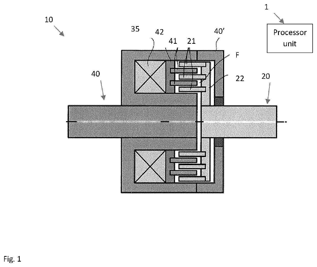
[0096]Referring to FIG. 1, there is illustrated a generic magnetorheological (MR) fluid clutch apparatus 10 configured to provide a mechanical output force based on a received input current provided by a processor unit 1 controlling the MR fluid clutch apparatus 10. The processor unit 1 is any type of electronic or electric device having controlling capability to control input current sent to the MR fluid clutch apparatus 10. In an embodiment, the processor unit 1 may receive signals from sensors, and compute data, for instance by way of firmware, to control the operation of the MR fluid clutch apparatus 10 based on settings, on requested assistance, etc, as will be explained hereinafter. The MR fluid clutch apparatus 10 has a driving member 20 with a disk 22 from which project drums 21 in an axial direction, this assembly also known as input rotor 20. The MR fluid clutch apparatus 10 also has a driven member 40 with a disk 42 from which project drums 41 intertwined with the drums 2...


PUM


Abstract

A system comprises one or more wearable devices including a first body interface adapted to be secured to a first bodily part. A second body interface is adapted to be secured to a second bodily part separated from the first bodily part by a physiological joint. One or more joints provide one or more degrees of freedom between the first body interface and the second body interface. A magnetorheological (MR) fluid actuator unit comprises one or more power sources. An MR fluid clutch apparatus receiving torque from the at least one power source, the at least one MR fluid clutch apparatus operable to generate a variable amount of torque transmission when subjected to a magnetic field. A transmission couples the MR fluid actuator unit to the wearable device for converting torque from the MR fluid actuator unit to relative movement of the body interfaces with respect to one another.

Description

CROSS-REFERENCE TO RELATED APPLICATION[0001]The present application claims the priority of U.S. Provisional Patent Application No. 62 / 505,392, filed on May 12, 2017, the contents of which are incorporated herein by reference.TECHNICAL FIELD[0002]The present application relates generally to the field of exoskeletons or orthoses / orthotics, and more particularly, to exoskeletons or orthosis systems using magnetorheological (MR) fluid clutch apparatuses.BACKGROUND OF THE ART[0003]The use of exoskeletons, orthoses or prostheses on humans may be desirable to enhance human capacities or restore human capabilities. In some cases, the objective is the reduction of the amount of human effort required to perform a task or function and in other cases the objective may be to amplify human capacity. In some cases, the objective is to restore human function. In some other cases, the exoskeleton could have the function of generating energy for a later use. In many cases, there is an exchange or ene...

Claims


Application Information

Patent Timeline
Patent Type & Authority Applications(United States)
IPC IPC(8): A61F2/70A61F5/01B25J9/00F16D37/02
CPCA61F2/70A61F5/0127A61F2002/6845A61F5/013F16D2037/004F16D37/02A61F2002/741A61F2005/0155A61F2002/745B25J9/0006A61F2002/6863A61H1/0262A61H1/0266A61H1/0274A61H1/0277A61H1/0281A61H3/00A61H2201/1207A61H2201/1616A61H2201/1642A61H2201/165A61H2201/1223A61F5/0102A61H2201/1238A61H2201/1246A61H2201/1409F16D2037/007A61F2/741A61F2/74
Inventor LAROSE, PASCALDENNINGER, MARCPLANTE, JEAN-SEBASTIENLUCKING BIGUE, JEAN-PHILIPPEVERONNEAU, CATHERINE
Owner EXONETIK INC
Why Eureka
Try Eureka