System and Method for Laser Induced Forward Transfer Comprising a Microfluidic Chip Print Head with a Renewable Intermediate Layer

a microfluidic chip and print head technology, applied in the field of laser induced forward transfer (lift), can solve the problems of inability to include an intermediate layer in the renewable lift system, limited efficiency of the current known lift method in some uses, and inability to reduce the flow rate of the reynolds. the effect of reducing the flow rate and suppressing the turbulence within the flow

Active Publication Date: 2020-03-05
PRECISE BIO INC +1
View PDF0 Cites 6 Cited by
  • Summary
  • Abstract
  • Description
  • Claims
  • Application Information

AI Technical Summary

Benefits of technology

[0009]The system disclosed herein is designed to meet this long-felt need. Instead of an arrangement that includes components such as block 100 or reservoir 260, the inventive system and method uses an integrated microfluidic chip (MFC) that controls and stabilizes the flow of ink. The MFC comprises three regions: an upper region comprising material that is substantially transparent at the laser output wavelength; a lower region comprising a small orifice through which droplets of ink are ejected in the direction of a receiving substrate; and a middle region into which two channels are embedded, with a portion of the channels open to each other along their sides over a region opposite the orifice. A fluid that absorbs strongly at the output wavelength of the laser flows through the upper channel, and ink flows through the lower channel. Laser light impinges on the fluid flowing through the upper channel, heating it and thereby leading to the formation of a transient pressure wave that forces ink out of the orifice, similar to the process that occurs in LIFT systems known in the art. The shallowness of the channels decreases the Reynolds number of the flows, thereby maintaining the ink thickness and velocity in front of the orifice by suppressing turbulence within the flow. Due to the small Reynolds numbers and the small size of the channels, the two fluids form uniform layers with stable laminar flow, so that no significant mixing occurs over the region in which the two channels are in contact.

Problems solved by technology

LIFT methods currently known in the art are of limited efficiency in some uses (particularly for bio-printing) because they tend to require a long preliminary preparation process, complex system design, and materials having a limited shelf life.
While Renewable LIFT allows high throughput and resolution of 10 μm or even less, it also suffers from some drawbacks.
Because of mixing, diffusion, and variable flow stability, it is not possible to include an intermediate layer in Renewable LIFT systems.
Thus, it is not possible to perform Renewable LIFT using inks that do not absorb strongly at the output wavelength of the laser.
Moreover, precise control of the width and flow velocity of the ink layer is difficult, and can vary over time due to such factors as the humidity, atmospheric pressure, etc.

Method used


Image

  • System and Method for Laser Induced Forward Transfer Comprising a Microfluidic Chip Print Head with a Renewable Intermediate Layer
  • System and Method for Laser Induced Forward Transfer Comprising a Microfluidic Chip Print Head with a Renewable Intermediate Layer
  • System and Method for Laser Induced Forward Transfer Comprising a Microfluidic Chip Print Head with a Renewable Intermediate Layer

Examples


embodiment 40

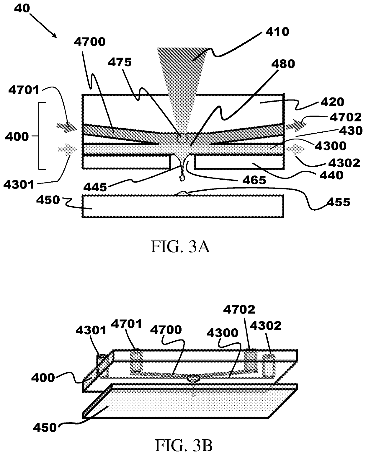
[0114]Reference is now made to FIG. 3, which presents a schematic diagram of a typical non-limiting embodiment 40 of a LIFT system that includes a microfluidic chip LIFT head of the present invention. A cross-sectional view is shown in FIG. 3A, while FIG. 3B shows a view from beneath the LIFT head that illustrates the inlet and outlet connections of the fluid flow channels of the MFC LIFT head. The system comprises an MFC 400, which serves as the LIFT head, and a receiving substrate 450 onto which ink is deposited from the LIFT head. The MFC comprises three regions: (1) a relatively thick upper region 420; (2) a relatively thin middle region 430 comprising at least two channels that pass through the body of the MFC: an intermediate layer channel 4700 and an ink channel 4300, which is disposed further from the upper region than is intermediate layer channel 4700; and (3) a relatively thin lower region 440 that includes an orifice 465 facing the receiving substrate.

[0115]A fluid conne...

embodiment 42

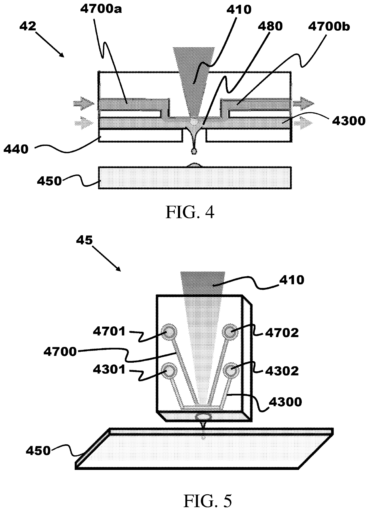
[0117]Reference is now made to FIG. 4, which presents a schematic illustration of a second non-limiting embodiment 42 of the system of the present invention. In the embodiment shown in the figure, the intermediate layer channel is divided into two portions, 4700a and 4700b, the interior end of each of which connects to the ink channel within the MFC. In this embodiment, fluid connection 480 is provided by the two connections between the intermediate layer and ink channels.

[0118]The MFC can be made of any appropriate material. The following non-limiting examples of materials of construction are given to assist the person of ordinary skill in the art how to make and use the invention disclosed herein; no limitations on physical or chemical properties such as rigidity or elasticity of materials suitable for use in the MFC are to be inferred from the following discussion. Typical materials of construction include polymers such as poly(methyl methacrlyate) (PMMA), cyclic olefin copolymer...

embodiment 45

[0120]Reference is now made to FIG. 5, which presents schematically a third non-limiting embodiment 45 of the LIFT head of the instant invention. In this embodiment, the ink jet is emitted from the narrow side of the MFC rather than from the broad side as shown in FIGS. 3 and 4.


PUM

PropertyMeasurementUnit
radiusaaaaaaaaaa
radiusaaaaaaaaaa
widthaaaaaaaaaa

Abstract

Methods and systems for Laser-Induced Forward Transfer are disclosed in which a microfluidic chip is used as the printing head. The head comprises a transparent upper region, a middle region comprising an intermediate layer channel and an ink channel in fluid connection with said intermediate layer channel, and a lower layer with an orifice in fluid contact with the ink channel. When material in the intermediate layer channel is irradiated by an energy source (typically a pulsed laser) at a spot opposite the orifice, the material is partially evaporated, creating a vapor bubble that creates a transient pressure increase when it collapses, thereby forcing ink out of the orifice and onto a receiving substrate.

Description

REFERENCE TO RELATED PUBLICATIONS[0001]This application claims priority from U.S. Provisional Pat. Appl. No. 62 / 485,952, filed 16 Apr. 2017, and which is incorporated by reference in its entirety.FIELD OF THE INVENTION[0002]This invention relates in general to means and methods for Laser Induced Forward Transfer (LIFT). It relates in particular to a microfluidic head for LIFT that incorporates a renewable intermediate layer.BACKGROUND OF THE INVENTION[0003]Laser Induced Forward Transfer (LIFT) is a printing process, particularly for 3-D printing, that is useful for printing of rigid, highly viscous, or sensitive materials. LIFT methods currently known in the art are of limited efficiency in some uses (particularly for bio-printing) because they tend to require a long preliminary preparation process, complex system design, and materials having a limited shelf life. A general review of the state of the art can be found in the article “Laser Direct-Write Techniques for Printing of Comp...

Claims


Application Information

Patent Timeline
Patent Type & Authority Applications(United States)
IPC IPC(8): B41J2/14
CPCB41J2/14104B41J2202/12C12M33/00B29C64/268B29C64/209B29C64/112B33Y10/00B33Y30/00B41J2002/14483B41M5/40B41J2/045B41M5/42
Inventor BATT, ARYEHEITAN, AMOSEISENBACH, ARIEL
Owner PRECISE BIO INC
Why Eureka
Try Eureka