Compact optical system for a motor-vehicle passenger compartment

a passenger compartment and compact technology, applied in the field of automobile industry, can solve the problems of reducing the comfort of users of motor vehicles, incompatibility of pixelated light sources, and scarce housing available in passenger compartments, and achieve the effect of reducing the bulk of such optical systems

Active Publication Date: 2020-03-12
VALEO VISION SA
View PDF0 Cites 2 Cited by
  • Summary
  • Abstract
  • Description
  • Claims
  • Application Information

AI Technical Summary

Benefits of technology

[0011]Thus, the ingenious use of the diffuser allows the optical system according to the first aspect of the invention to decrease a luminance of the light source intended to collaborate therewith. Furthermore, the optical system according to the first aspect of the invention is configured to preserve the pixelization of the light source. In other words, a shape and / or a geometry of the light source intended to collaborate with the optical assembly is substantially preserved at the exit of the optical assembly and / or of the optical system. Therefore, the light rays that penetrate into the optical system according to the first aspect of the invention exit therefrom with a decreased luminance and while preserving substantially the same spatial distribution as they had on entering. In other words, the optical system is configured to perform a homothetic transformation of the light source with which it is intended to collaborate—and preferably a homothetic transformation of the type of an enlargement. The use of the diffuser furthermore allows an opening angle of the light rays passing through the optical system to be modified.
[0014]According to the first aspect of the invention, the optical system allows the etendue of the light beam that passes through said optical system to be increased between (i) an entrance face located on the side of the light source intended to collaborate with the optical system and (ii) the exit face of the optical system.
[0017]According to one main advantage of the first aspect of the invention, such an optical system is compact and thus allows the bulk of such an optical system to be decreased with respect to those employed in known interior lighting devices. Furthermore, the production of such an optical system allows manufacturing cost to be limited.
[0019]the optical assembly comprises (i) a first portion optically located between the light source and the diffuser, the first portion being able to anamorphose the light source, and (ii) a second portion optically located between the diffuser and the exit face of the optical assembly, the second portion being an optic for projecting the light rays scattered by the diffuser. The adverb “optically” is here understood to mean in the direction of travel of the light rays in the optical system during its normal use. The first portion of the optical assembly in particular allows a real image of the light source with which the optical system is intended to collaborate to be created, this image being larger than the actual size of the source; the light cone of such a real image of the light source is smaller than the light cone of said light source as such.
[0028]the diffuser is a “through” diffuser, the light rays incident on a face of incidence of the diffuser being scattered at a face that is opposite to the face of incidence with respect to the first portion of the optical assembly. This advantageous configuration allows an optical system of more compact geometry to be produced;
[0037]Thus, the lighting device according to the second aspect of the invention makes it possible to provide an interior light, for a motor-vehicle passenger compartment, that decreases the luminance of the light sources used and that thus makes the latter compatible with such a use in a motor-vehicle passenger compartment.

Problems solved by technology

Thus, although the luminous functionalities provided by interior lighting devices are increasing in number in order to meet the demands of manufacturers and users of motor vehicles, the housings available in passenger compartments are at the same time becoming scarcer.
However, the conjugation of their small size and their high luminance makes such pixelated light sources incompatible with a use in the passenger compartment of a motor vehicle, because they present a potential risk to the human eye and they decrease the comfort of users of the motor vehicle.

Method used


Image

  • Compact optical system for a motor-vehicle passenger compartment
  • Compact optical system for a motor-vehicle passenger compartment

Examples


first embodiment

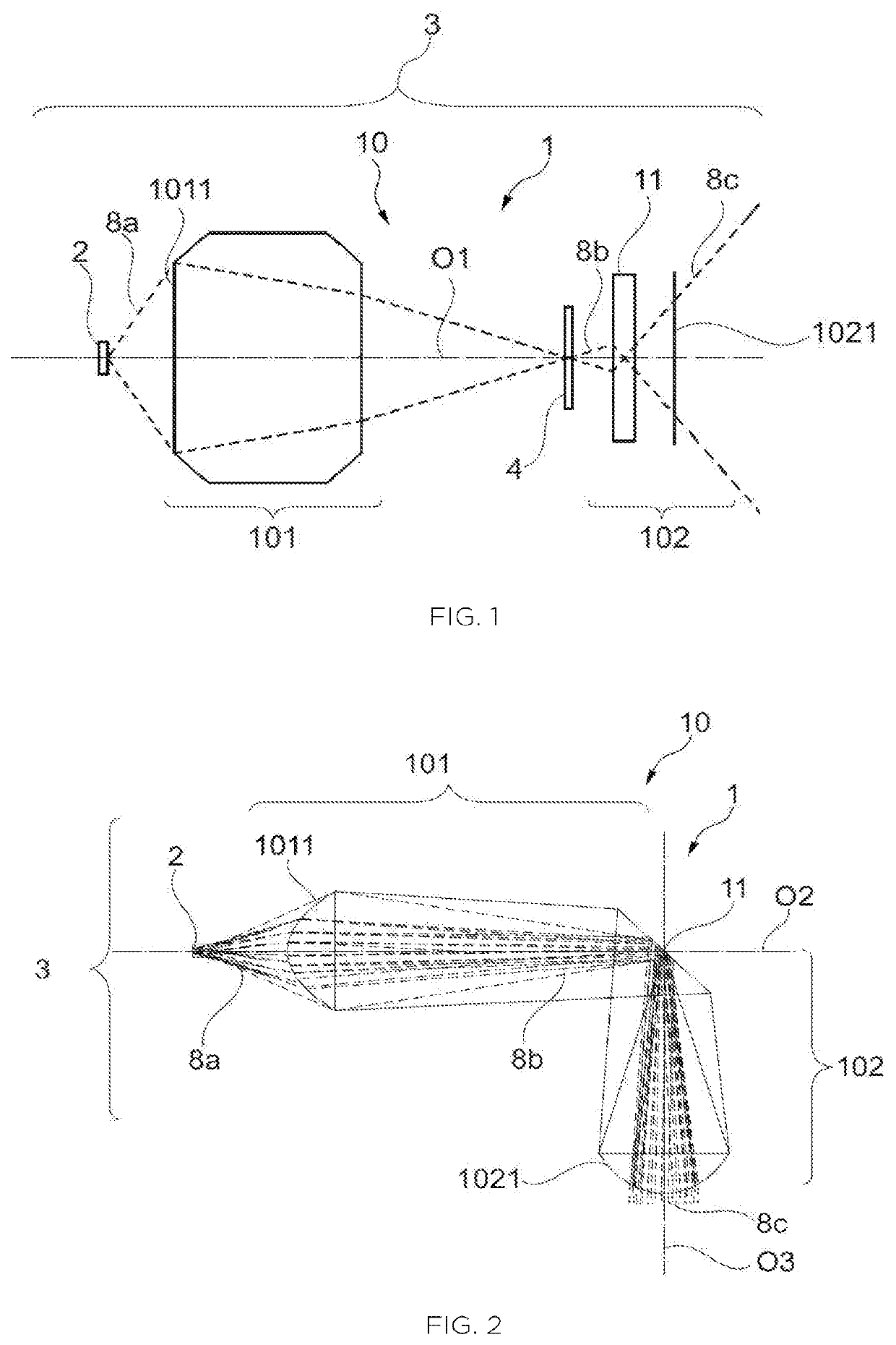
[0063]FIG. 1 illustrates a schematic version of the optical system 1 implemented in an interior lighting device 3, and in which the optical system 1 lies on a single optical axis O1.

[0064]The first portion 101 of the optical assembly 10 is located at distance from the light source 2 and possesses a large admission angle, so that most—and preferably all—of the light rays 8a generated by the light source 2 penetrate into the optical system 10 through the entrance face 1011 of the first portion 101 of the optical assembly 10. The first portion 101 is formed by one or more lenses and / or by one or more reflective surfaces, in order to form the real image 4 of the light source 2 in a position that is optically intermediate between the first portion 101 and the diffuser 11, along the single optical axis O1.

[0065]All of the incident light rays 8b that reach the diffuser 11 beyond the real image 4 of the light source 2 together form a cone an opening angle of which is smaller than that of a ...

second embodiment

[0069]FIG. 2 illustrates a schematic version of the optical system 1 implemented in an interior lighting device 3, and wherein the optical system 1 has a dog-legged configuration.

[0070]The first portion 101 of the optical assembly 10 is located at distance from the light source 2 and possesses a large admission angle, so that most—and preferably all—of the light rays 8a generated by the light source 2 penetrate into the optical system 10 through the entrance face 1011 of the first portion 101 of the optical assembly 10. The first portion 101 is formed by one or more lenses and / or by one or more reflective surfaces in order to form the real image of the light source 2 at the diffuser 11, along a first optical axis O2 that extends in a first direction.

[0071]The diffuser 11 of the optical system 10 illustrated in FIG. 2 is reflective and it is oriented with respect to the first optical axis O2 so as to make a nonzero angle that is preferably comprised between 20° and 70°. In order to m...

third embodiment

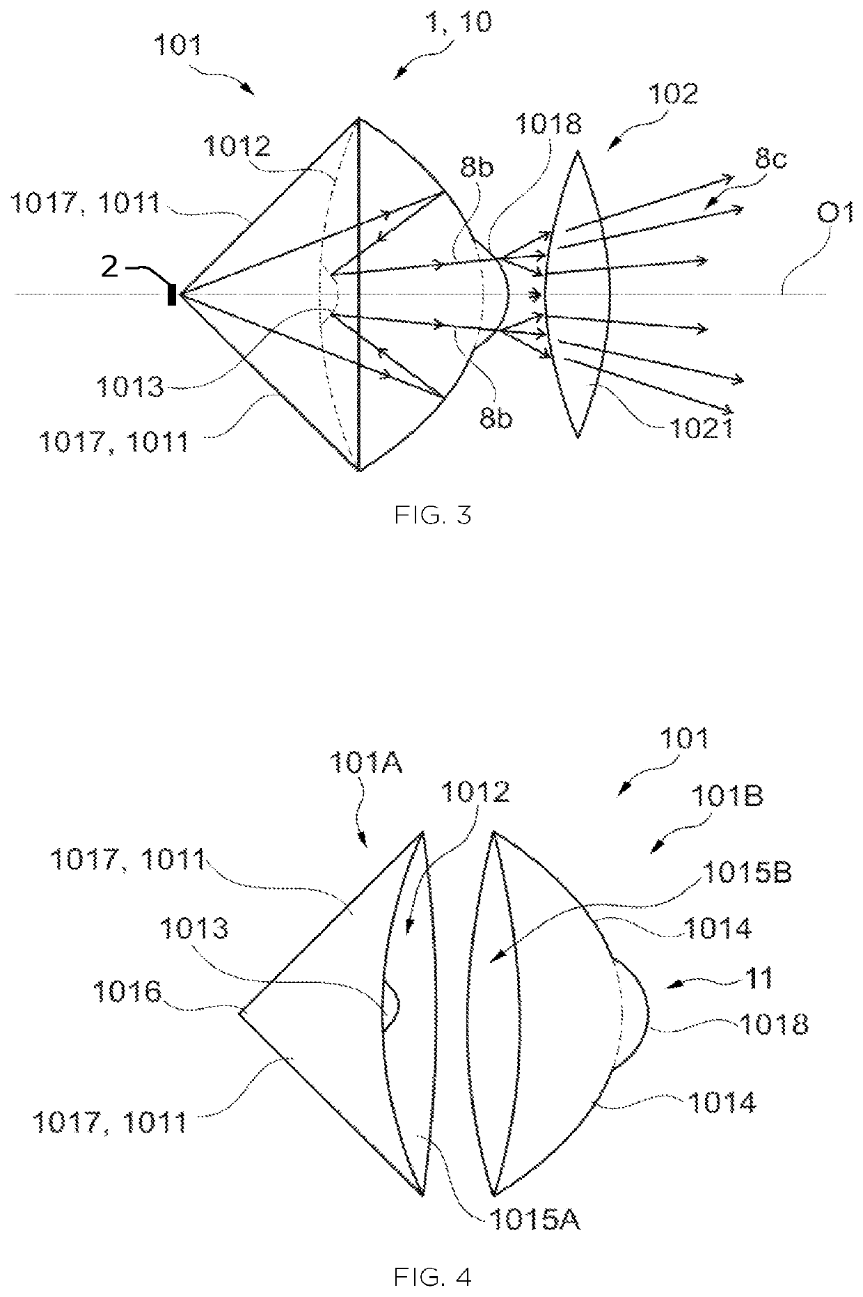
[0087]The optical system illustrated in this third embodiment is particularly compact and economical to manufacture, because it results from the assembly of the two optical parts 101A, 101B and from their combination with the second portion 102 of the optical assembly 10.

[0088]In summary, the invention in particular relates to an optical system 1 and to an interior motor-vehicle lighting device 3 comprising a light source 2 coupled to such an optical system 1. The optical system 1 comprises a first portion 101 of an optical assembly 10 that allows a real image 4 of the light source 2 to be projected into proximity to a diffuser 11 of the optical system 1. The optical assembly 10 of the optical system 1 also comprises a second portion 102 that plays the role of a projecting optic in order to project, out of said optical system 1, a real image of the real image of the light source 2 formed in proximity to the diffuser 11. The optical system 1 according to the invention allows a lumina...


PUM

PropertyMeasurementUnit
angleaaaaaaaaaa
angleaaaaaaaaaa
angleaaaaaaaaaa

Abstract

An optical system and an interior lighting device for a motor vehicle including a light source coupled to such an optical system. The optical system includes a first portion of an optical assembly that allows a real image of the light source to the enlarged and projected into proximity to a diffuser of the optical system. The optical assembly also includes a second portion that plays the role of a projecting optic to project out of the optical system a real image of the of the light source formed in proximity to the diffuser. The optical system allows a luminance of the light source of the interior lighting device to be decreased while preserving its pixelization, allowing light sources based on light-emitting diodes and driven with a high-amperage electrical current to be used in motor-vehicle passenger compartments without any risk to the occupants.

Description

TECHNICAL FIELD[0001]The present invention relates to the field of the automotive industry, and more particularly relates to interior lighting devices, in particular those for motor-vehicle passenger compartments.PRIOR ART[0002]Known motor-vehicle passenger compartments comprise many interior lighting devices in order to allow a plurality of luminous functions to be performed. By way of nonlimiting examples of known luminous functions, certain interior lighting devices allow luminous indications to be displayed from or on a wall of the passenger compartment; certain interior lighting devices allow manual controls of the motor vehicle to be lit up; and certain other interior lighting devices are dedicated to lighting one portion of a space inside the passenger compartment of the motor vehicle.[0003]One particularity common to all these devices is that they must meet strict dimensional constraints as a result of the increase in the number of electrical devices—whether used for lightin...

Claims


Application Information

Patent Timeline
Patent Type & Authority Applications(United States)
IPC IPC(8): B60Q3/62F21V3/04F21V7/28B60Q3/74
CPCB60Q3/62F21V7/28B60Q3/74F21W2106/00F21V3/049F21S8/00F21V5/08F21W2107/10F21Y2115/10G02B5/0221G02B19/0028B60Q3/60B60Q3/76F21V5/008F21V7/0041F21V7/0091G02B19/0061G02B5/0278
Inventor ALBOU, PIERRELEFAUDEUX, NICOLAS
Owner VALEO VISION SA
Why Eureka
Try Eureka