Supercharge Your Innovation With Domain-Expert AI Agents!

Catalyst deterioration diagnosis method and catalyst deterioration diagnosis system

a technology of catalyst deterioration and diagnosis method, which is applied in the direction of electrical control, separation processes, instruments, etc., can solve the problems of measurement error, osc method is liable to be affected, and the error in estimating the performance of a twc is increased, so as to achieve high accuracy and high accuracy

Active Publication Date: 2020-03-12
NGK INSULATORS LTD
View PDF0 Cites 4 Cited by
  • Summary
  • Abstract
  • Description
  • Claims
  • Application Information

AI Technical Summary

Benefits of technology

The present invention provides a method and system for diagnosing the deterioration of a catalyst used in an internal combustion engine. The method involves monitoring the temporary increase of a detection value of a gas sensor that has sensitivity to ammonia, which is output from the catalyst. The detection value is acquired during times when there is an increase in the engine's load, such as when the vehicle is accelerating or when the engine is being driven under specialized conditions. The system includes a gas sensor and control device, which work together to accurately diagnose the degree of deterioration of the catalyst and alert the operator when necessary. This allows for timely maintenance and replacement of the catalyst, which can prolong the life of the engine and reduce emissions.

Problems solved by technology

This may increase an error in estimating performance of a TWC.
Further, the OSC method is liable to be affected by a measurement error caused due to deterioration of the O2 sensors on an upstream side and a downstream side of a TWC.
Such a difference is liable to be affected by a composition of gasoline or engine oil, and therefore coping with the difference through correction is difficult.
A determination error about a rich state and a lean state directly leads to a diagnosis error of the OSC method.
Further, the O2 sensor on a downstream side may wrongly determine that a state is closer to a rich state than an actual state, under influence of hydrogen or the like generated in a TWC.
Further, when the engine is stopped for a long period, a large amount of CO2 may be absorbed into a site where O2 is supposed to be absorbed.
When a diagnosis is started in a state where the absorbed CO2 is not sufficiently eliminated after the engine is started, a diagnosis error is increased.
Further, when an intake air volume of the engine is large, a ratio of oxygen not absorbed into ceria in the entire oxygen in the intake air is large.
Therefore, an error in estimating OSC may be increased.
This is more liable to be seen as a problem particularly when exhaust gas recirculation (EGR) is used.
Reduction in an absorption rate of O2 is also affected by a temperature of an exhaust gas, which may lead to an error in estimating OSC.
Further, in the OSC method, there are limited opportunities where conditions (such as an intake air volume, a temperature of an exhaust gas, and an engine speed) suited for a diagnosis are satisfied.
Specifically, a diagnosis cannot be conducted with sufficient accuracy unless an engine speed is kept high in a certain degree and a vehicle speed is kept substantially constant (e.g., 60 km / h to 90 km / h) for a certain period of time.
Further, a driving state (such as an intake air volume, a temperature of an exhaust gas, and an engine speed) in which such active OBD can be applied is strictly limited, and thus opportunities to conduct a diagnosis are also strictly limited.
However, a phenomenon caused due to deterioration of a catalyst is not only reduction in NOx removal performance.
However, preparing a gas sensor only slightly affected by interference between components may be difficult, depending on a composition of an exhaust gas, in particular an oxygen ratio of the exhaust gas.
This interference property between components leads to reduction in accuracy of a catalyst deterioration diagnosis.

Method used


Image

  • Catalyst deterioration diagnosis method and catalyst deterioration diagnosis system
  • Catalyst deterioration diagnosis method and catalyst deterioration diagnosis system
  • Catalyst deterioration diagnosis method and catalyst deterioration diagnosis system

Examples


Embodiment Construction

[0029]An embodiment of the present invention will be described below with reference to the drawings.

[0030](Configuration)

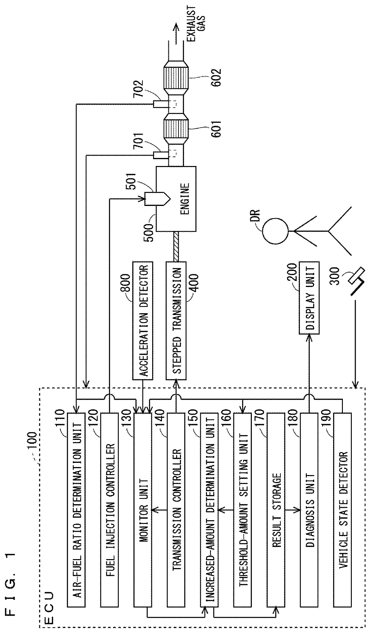
[0031]FIG. 1 is a diagram schematically illustrating a configuration of a vehicle (system) according to this embodiment. In this embodiment, a vehicle is an automobile driven by a driver DR. The automobile includes a gasoline engine 500 (internal combustion engine) including a fuel injection device 501, a stepped transmission 400 connected to the gasoline engine 500, a TWC 601 (catalyst), and a catalyst degradation diagnosis system to be described later.

[0032]The vehicle may further include an accelerator pedal 300 (drive operation device) operated by the driver DR, an additional catalyst 602, an air-fuel ratio sensor 701, and an acceleration detector 800. The accelerator pedal 300 is a pedal operated by the driver DR to drive a vehicle. The additional catalyst 602 is disposed on a downstream side of the TWC 601. For example, the additional catalyst 602 is a TWC, ...


PUM


Abstract

A catalyst deterioration diagnosis method is a method for a system. The system includes a stepped transmission or a continuously variable transmission connected to an internal combustion engine, a catalyst into which an exhaust gas from the internal combustion engine is introduced, and a gas sensor having sensitivity to ammonia that outputs a detection value corresponding to a component of an exhaust gas that has passed through the catalyst. The catalyst deterioration diagnosis method includes the following steps. Monitoring of temporary increase of a detection value of the gas sensor is started, and thereby a temporarily increased amount of the detection value of the gas sensor is acquired. The monitoring is started when upshifting of the stepped transmission or pseudo-upshifting of the continuously variable transmission is performed. Whether or not the temporarily increased amount is larger than a threshold amount is determined.

Description

CROSS-REFERENCE TO RELATED APPLICATION[0001]The present application claims priority from Japanese application JP2018-167739, filed on Sep. 7, 2018, the contents of which is hereby incorporated by reference into this application.BACKGROUND OF THE INVENTIONField of the Invention[0002]The present invention relates to a catalyst deterioration diagnosis method and a catalyst deterioration diagnosis system, and more particularly to a catalyst deterioration diagnosis method and a catalyst deterioration diagnosis system for a catalyst into which an exhaust gas from an internal combustion engine is introduced.Description of the Background Art[0003]A gasoline engine emits an exhaust gas containing toxic substances, namely, nitrogen oxide (NOx), total hydrocarbon (THC), and carbon monoxide (CO). A catalyst that collectively removes these three contained substances, i.e., a three way catalyst (TWC), is mounted in many gasoline engine vehicles. The three way catalyst has a honeycomb structure. T...

Claims


Application Information

Patent Timeline
Patent Type & Authority Applications(United States)
IPC IPC(8): F01N11/00B01D53/94G01M15/10F02D41/14F01N3/10
CPCF02D41/1463F02D2041/1468F01N11/00G01M15/102F01N3/101B01D53/9454F01N3/20F01N2550/02F01N2560/021F01N2900/0416F01N2560/026F01N2900/1402F01N2900/1616F01N2900/10Y02A50/20Y02T10/12Y02T10/40
Inventor OKAMOTO, TAKUNAKASONE, OSAMU
Owner NGK INSULATORS LTD
Features
  • R&D
  • Intellectual Property
  • Life Sciences
  • Materials
  • Tech Scout
  • Unparalleled Data Quality
  • Higher Quality Content
  • 60% Fewer Hallucinations
Learn More