
Green Cycle Heat Pump Engine

a heat pump engine and green cycle technology, applied in the direction of gas cycle refrigeration machines, hot gas positive displacement engine plants, refrigeration machines, etc., to achieve the effect of maximizing the heat transfer

Inactive Publication Date: 2020-03-12
GREEN JR DARRELL HENRY +2
View PDF0 Cites 1 Cited by
  • Summary
  • Abstract
  • Description
  • Claims
  • Application Information

AI Technical Summary

Benefits of technology

The invention can be used in a variety of ways as a heat transfer engine or heat pump, or a combination of both. It can be attached to a vessel, human body, or a power source. It can be used to generate electricity or cool down a heat sink. It can also be used as a part of a larger heat pump system or for industrial engines. The technical effects of the invention include efficient heat transfer and flexibility in power source options.

Problems solved by technology

However, due to the complexity of the internal combustion engine and the danger of the steam engine, the sealed heat cycle engine has held a niche for applications needing multiple fuel types, low temperature differences or the use of external heat sources.

Method used


Image

  • Green Cycle Heat Pump Engine
  • Green Cycle Heat Pump Engine

Examples


Embodiment Construction

)

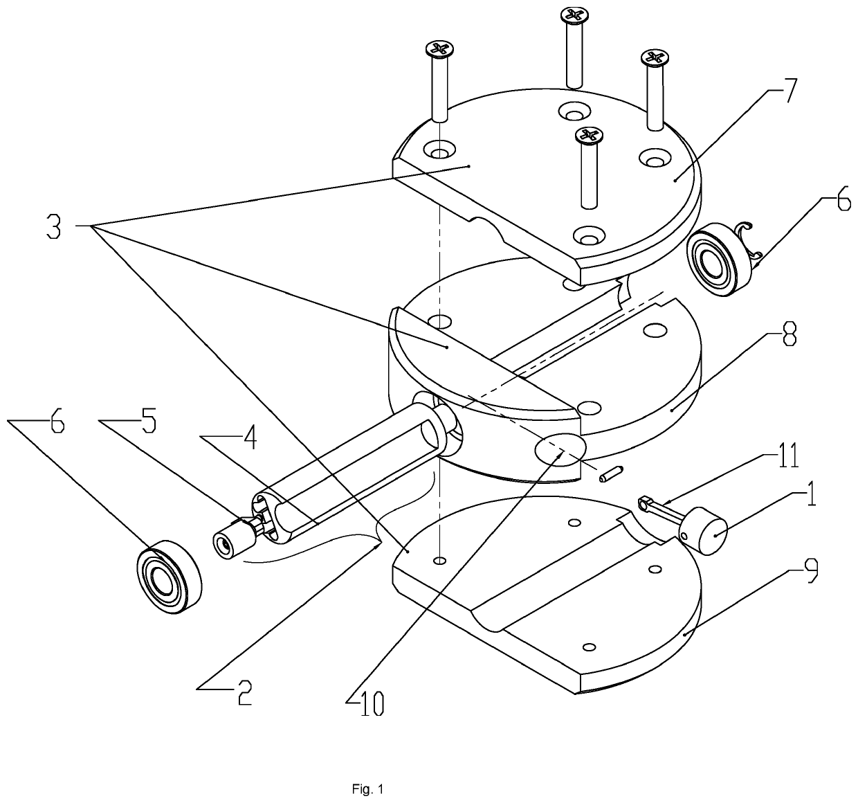
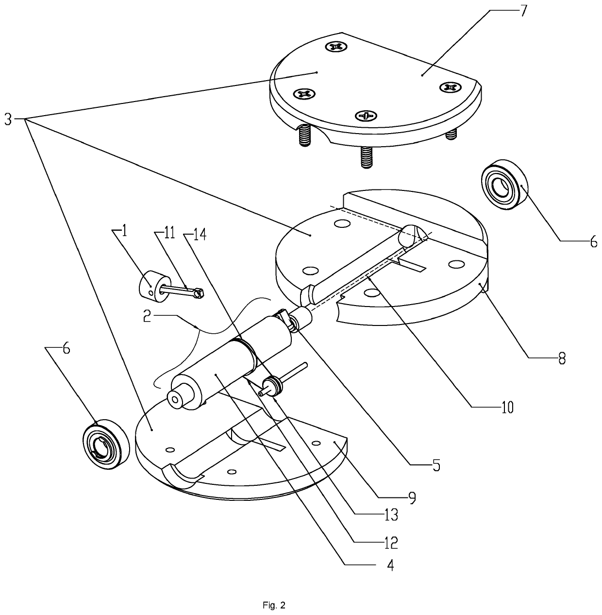
[0021]The number of pistons will depend on the application. However, the design may use a single piston (1) to manipulate the available volume within the chamber (10). The piston (1) is attached to a connecting rod (11) connected to a crank shaft (5)-cam shaft (4) combination (described here as rotary displacer) (2). The piston's (1) shape may vary due to size and application and may be a tympanic drum. The piston (1) resides in a channel perpendicular to the chamber containing the crank shaft (5)-cam shaft (4) rotary displacer (2). The piston (1) may extend when driven by an expansion of the working fluid during use as a rotary power generator or may extend due to mechanical propulsion to create a low pressure in the working fluid when used as a heat pump. The piston (1) may retract when allowed by a low pressure when used as a rotary generator or may retract due to mechanical propulsion to create a high pressure in the working fluid when used as a heat pump. The cam (4) of the ro...


PUM


Abstract

A single piston (1), rotary displacer (2), heat cycle / transfer engine, using a fixed volume of working fluid, in a single L shape tubular chambered (10), three zone (7)(8)(9), sealed housing (3). The rotary displacer (2) consists of a displacer cam (4) and a crank shaft (5) supported by a variable number of rotary bearings (6), the number and type of which depends on the size and rotational speed of the completed unit. The sealed housing (3), consisting of three zones, where one faces a heat source side (7), one acts an insulating barrier (8) and one acts as a heat sink (9). Movement of the rotary displacer (2) transports the contained working fluid to the exposed surfaces of the heat source side (7) and the heat sink (9) sequentially, while the incorporated crank shaft (5) drives the single piston (1), via a connecting rod (11), which allows for the manipulation of the corresponding expansion and contraction of the working fluid. The engine can use the transfer of heat, the Carnot Heat Cycle, to generate rotational (or linear) power or act as a heat pump / refrigeration unit. When used to produce rotational power, the initial rotational energy may be provided by a loop of Nitinol (12) or similar shape memory alloy to avoid a stall caused by the working fluid being exposed to the heat source side and heat sink side equally. The Nitinol loop (12) may ride on a second shape memory alloy ring (14), which allows it to disengage at higher temperatures and rotational speeds, effectively acting as a clutching mechanism. The invention is scalable to include nano-devices and micro electromechanical systems (MEMS), through large scale heat recovery systems.

Description

CLASSIFICATIONS[0001]F02G1 / 043 Hot gas positive-displacement engine plants of closed-cycle type the engine being operated by expansion and contraction of a mass of working gas which is heated and cooled in one of a plurality of constantly communicating expansible chambers[0002]F25B9 / 14 Compression machines, plant, or systems, in which the refrigerant is air or other gas of low boiling point characterized by the cycle used[0003]Y02E10 / 46 Conversion of thermal power into mechanical power, e.g. Rankine[0004]F03G7 / 065 Mechanical-power-producing mechanisms, not otherwise provided for or using energy sources not otherwise provided for using expansion or contraction of bodies due to heating, cooling, moistening, drying or the like using a shape memory elementBACKGROUND OF THE INVENTIONField of the Invention[0005]The invention is related to a group of devices utilizing the Carnot heat cycle, where variations in the pressure of the working fluid is caused by exposure to an external heat sour...

Claims


Application Information

Patent Timeline
Patent Type & Authority Applications(United States)
IPC IPC(8): F25B9/14F02G1/043F03G7/06
CPCF25B9/14F02G1/043F03G7/065F25B2309/001
Inventor GREEN, JR., DARRELL HENRYMERCADAL, CHRISTOPHER LEELYONS, AMIE
Owner GREEN JR DARRELL HENRY
Learn More