Eureka AIR delivers breakthrough ideas for toughest innovation challenges, trusted by R&D personnel around the world.

Electronically controlled transformer

Active Publication Date: 2020-03-12
LU JUNHONG
View PDF7 Cites 0 Cited by
  • Summary
  • Abstract
  • Description
  • Claims
  • Application Information

AI Technical Summary

Benefits of technology

This patent describes a technical solution for regulating the voltage in an AC power supply. The solution uses a control chip and an optical coupler to turn off or on a component to control the output voltage. This helps to regulate the voltage and transform it for use. The solution has the benefits of simple lines, low cost, small size, and light weight. It also solves issues with traditional iron core transformers, making it a strong market option.

Problems solved by technology

The existing mechanical transformers are mainly made by winding coil round the core, the core has large volume, heavy weight, high energy consumption, low power factor, as well as inconvenient transportation, installation and use.
However, the aforethe switching power supplies have complex lines and high costs, some cannot work under high power and high current as limited to conditions, devices and circuits; some can work under high current and high power, but they cannot be small and light as limited to the working conditions of devices, they are still large sized and heavy, the defects in the iron core transformer cannot be solved basically.

Method used


Image

  • Electronically controlled transformer
  • Electronically controlled transformer
  • Electronically controlled transformer

Examples


Embodiment Construction

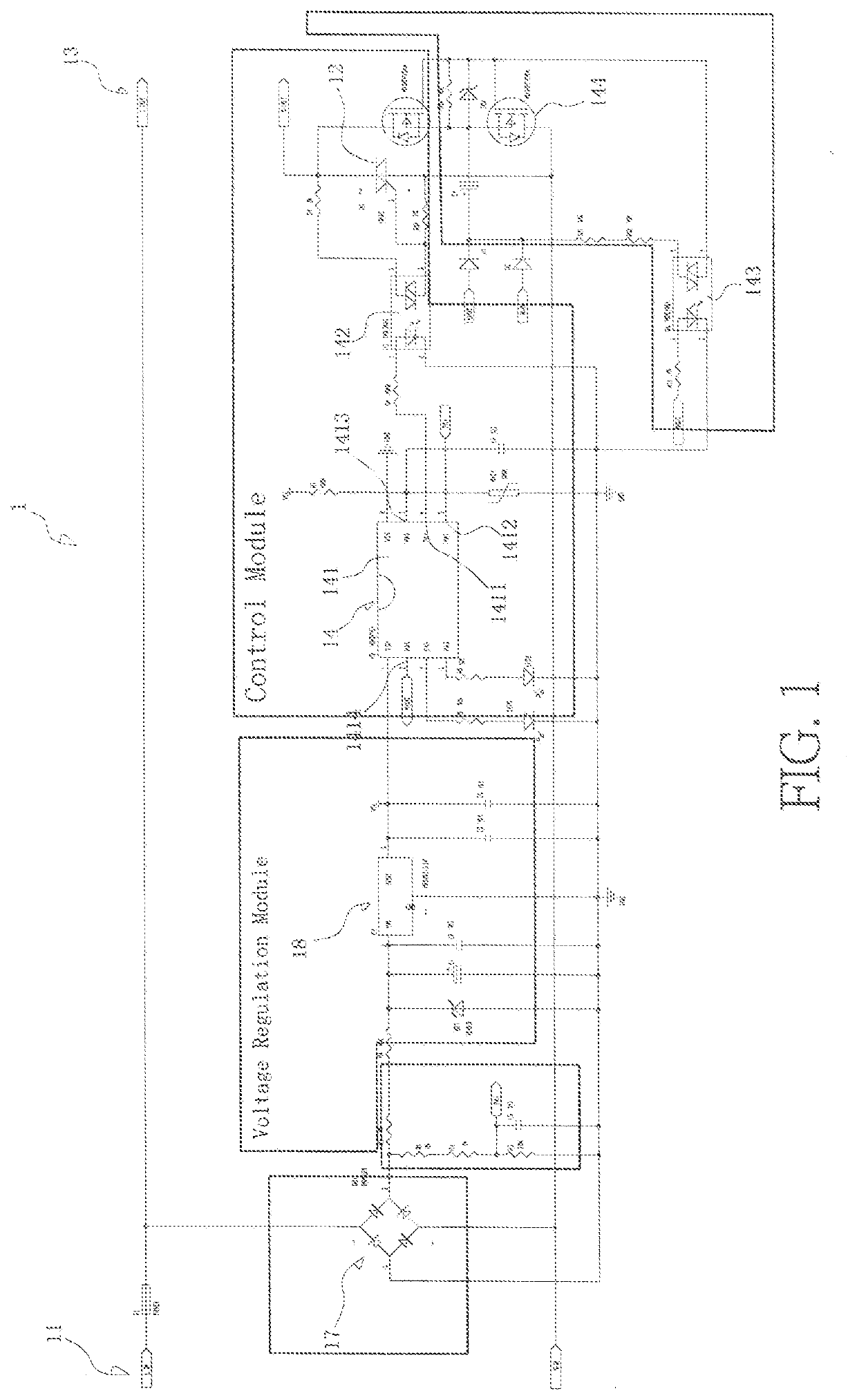
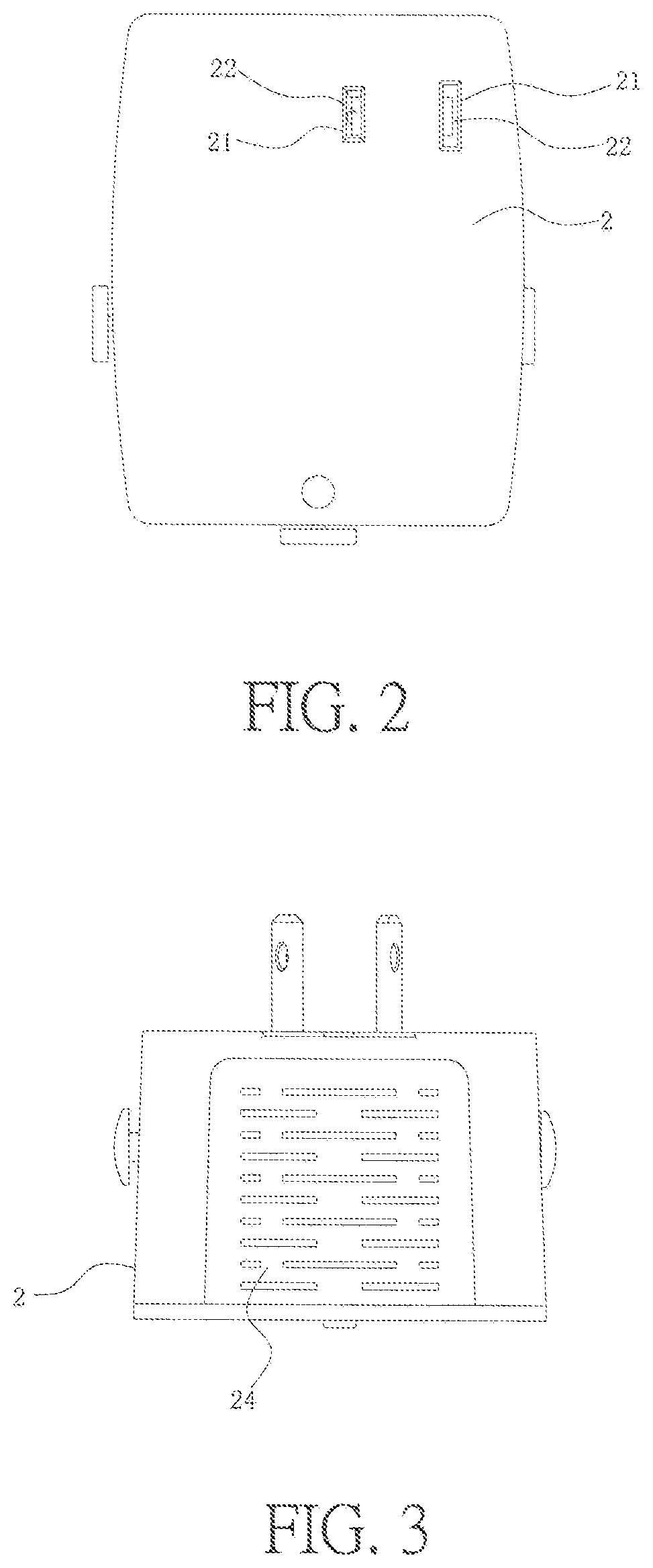
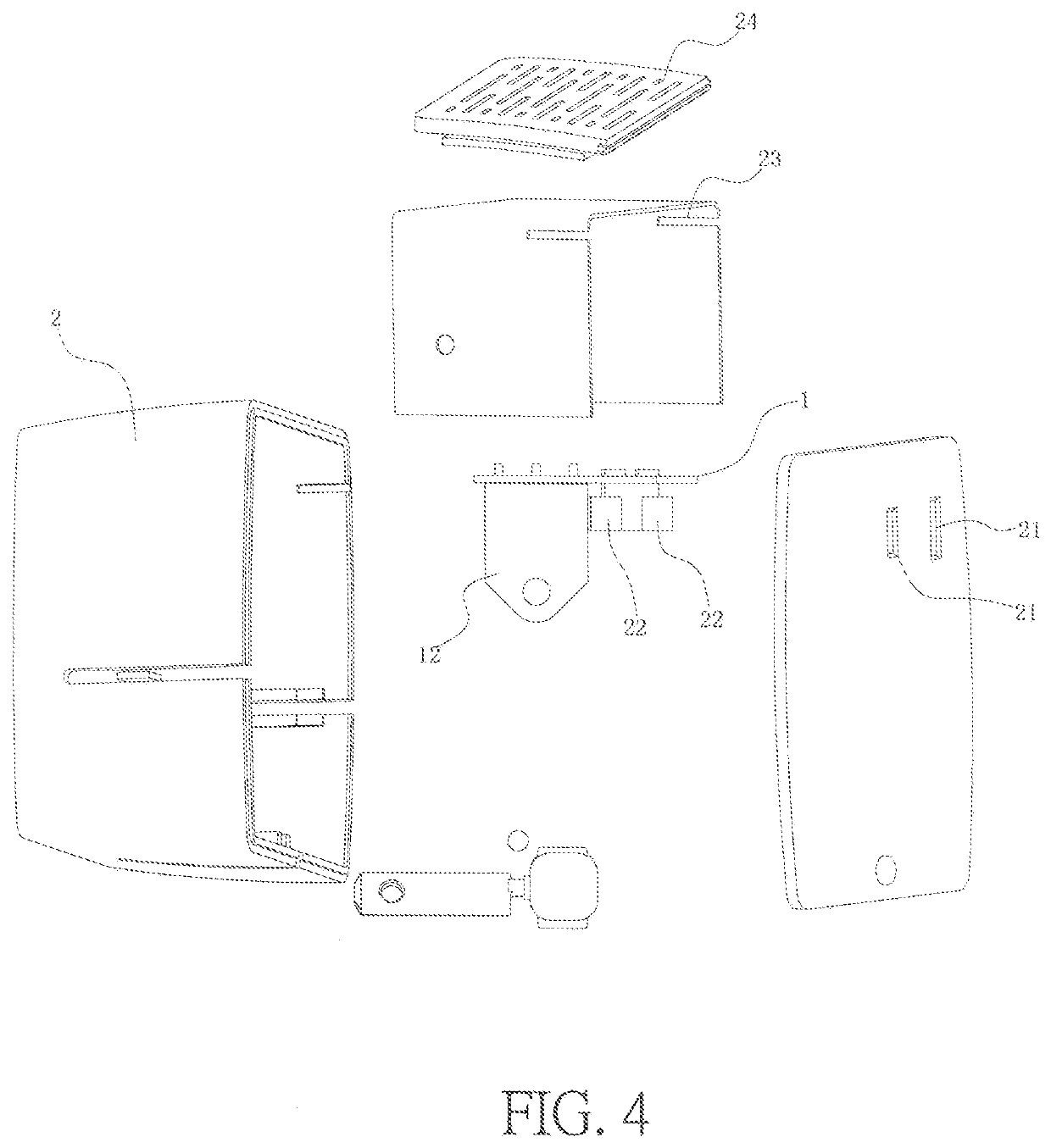
[0019]FIGS. 1-4 show an electronically controlled transformer, which is used for AC power supply, cutting off the sinusoidal waveform of voltage to change the RMS voltage. The electronically controlled transformer comprises a casing 2, socket holes 21 and socket tabs 22 for output and a circuit board 1. The circuit board 1 is provided with an input terminal 11, a silicon controlled rectifier 12 or field-effect transistor, an output terminal 13 connected to the silicon controlled rectifier 12 or field-effect transistor and a control module 14 for controlling the silicon controlled rectifier 12 on / off or field-effect transistor on / off. The socket holes 21 and socket tabs 22 act as the output terminal 13.

[0020]The live wire and neutral wire of the input terminal 13 are connected by a rectifier or bridge rectifier 17. The voltage positive output of the rectifier or bridge rectifier 17 is connected to a voltage regulation module 18. The voltage regulation module 18 is connected to the co...


PUM

PropertyMeasurementUnit
Timeaaaaaaaaaa
Timeaaaaaaaaaa
Timeaaaaaaaaaa

Abstract

An electronically controlled transformer, which is used for AC power supply, cutting off the sinusoidal waveform of voltage to change the RMS voltage. The electronically controlled transformer comprises a casing, socket holes and socket tabs for output and a circuit board. The circuit board is provided with an input terminal, a silicon controlled rectifier or field-effect transistor, an output terminal and a control module. The live wire and neutral wire of input terminal are connected by a rectifier or bridge rectifier. The positive output of rectifier or bridge rectifier is connected to a voltage regulation module. The voltage regulation module is connected to a control module. The control module comprises a control IC and a trigger and driving part. The trigger and driving part has an optical coupler. The switching pin of control IC is connected to the transmitting terminal of optical coupler.

Description

BACKGROUND OF INVENTION1. Field of the Invention[0001]The present invention relates generally to the technical field of electronics and power, and more particularly to an electronically controlled transformer.2. Description of Related Art[0002]The transformer is an extensively used transform equipment. The existing mechanical transformers are mainly made by winding coil round the core, the core has large volume, heavy weight, high energy consumption, low power factor, as well as inconvenient transportation, installation and use. Different switching power supplies (i.e. electronic transformers) are also transform equipment, which can convert AC into DC voltage, and the electronic devices convert frequency and modulate width, and then the transformed high frequency voltage is rectified and filtered to obtain the required DC voltage. However, the aforethe switching power supplies have complex lines and high costs, some cannot work under high power and high current as limited to conditi...

Claims


Application Information

Patent Timeline
IPC IPC(8): H01F27/42H02M1/10
CPCH01F27/425H02M2001/0093H02M1/10H01F1/0045H01F41/00C12N9/0061C12N9/96C12Y110/03002C02F3/342H02M5/293H02M5/257H02M1/0006H02M1/0093H02J7/007H02J7/005H01F27/28H02M1/08
Inventor HAO, LONG LONG
Owner LU JUNHONG
Why Eureka
Eureka Blog
Learn More