Eureka AIR delivers breakthrough ideas for toughest innovation challenges, trusted by R&D personnel around the world.

Portable lower limb therapy device

a therapy device and lower limb technology, applied in the field of portable therapy devices, can solve the problems of short therapy sessions, many insurance companies will not pay for a cpm device, and provide feedback loops, and achieve the effect of facilitating the performance of rehabilitation exercises

Active Publication Date: 2020-03-19
MARTI EDUARDO M +1
View PDF12 Cites 5 Cited by
  • Summary
  • Abstract
  • Description
  • Claims
  • Application Information

AI Technical Summary

Benefits of technology

The present invention is about a portable device that can help people with lower limb issues do rehabilitation exercises at home. This device can combine different types of movements and provide dynamic and static stretching. It consists of a support base that can slide on a smooth surface and a pulley system that can flex the platform member with the help of a mechanical force. The technical effect of this invention is to provide a versatile and efficient tool for lower limb therapy.

Problems solved by technology

Unfortunately, often times therapy sessions are cut short prior to the completion of the recovery process.
This can be due to a variety of reasons, such as limited treatment sessions approved by insurance companies, lack of transportation, inclement weather, illness, or inability to take days off from work to attend therapy sessions at the clinic.
Nonetheless, there are two types of motions that are viable, and typically, these devices generally only cover one or the other type of motion.
Unfortunately, many insurance companies will not pay for a CPM device.
These types of devices are external devices that are not used to rehabilitate the patients injured knee joint at home and they do not provide a feedback loop to the patient.

Method used


Image

  • Portable lower limb therapy device
  • Portable lower limb therapy device
  • Portable lower limb therapy device

Examples


Embodiment Construction

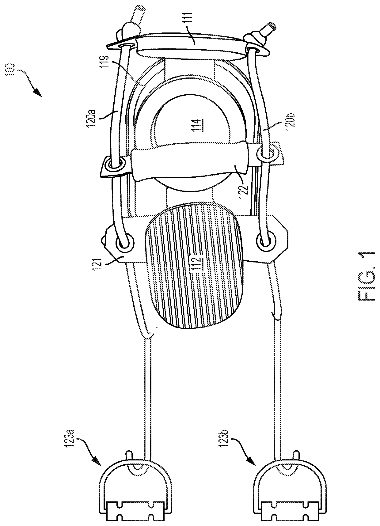
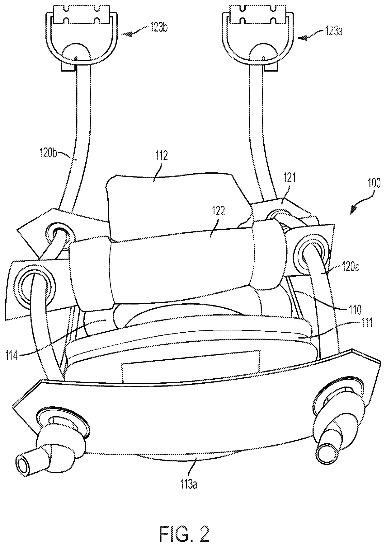
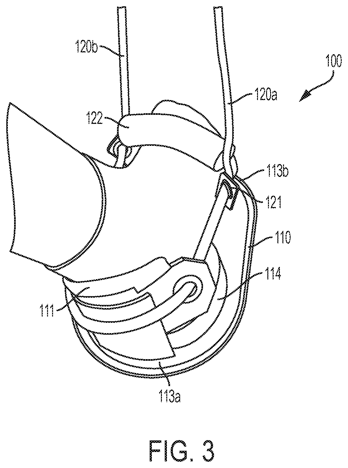
[0023]Referring now to the drawings and, in particular, FIGS. 1, 2, 3 and 4, a portable lower limb therapy device 100 built in accordance with a front handle embodiment is shown having a support base and a pulley system. The support base includes a slider 110 having a platform member 112 fixably mounted on top of it and a back panel 111 extending up from a location at or behind the proximal edge 113a (i.e., on the opposite side of the proximal edge 113a as the distal edge 113b). The support base has a proximal edge 113a and a distal edge 113b, which may be formed as the rear and front edges of the slider 110, respectively.

[0024]The slider 110 may define a rigid, slightly curved member having a smooth bottom surface that limits friction and allows it slide and glide when placed on other surfaces. The slider 110 may be constructed of hard plastic and the back panel 111, platform member 112, heel cup 114, and foot pad 114 may be constructed out of a substantially firm yet pliable foam....


PUM


Abstract

A portable lower limb therapy device having a support base and a pulley system. The support base includes a platform member fixably mounted on top of a slider and a heel panel positioned behind the platform member. The heel panel, which sits orthogonally relative to the platform member, is attached to the slider so as to extend from the rear end of the slider. The pulley system defines a closed force transfer system that is integrated with the support base. The pulley system employs a cord member, a support member, a cross member, and two handles and is configured to transfer force applied behind the heel panel to the platform member as well as force applied above a user's foot that is positioned on top of the platform member to the platform member.

Description

BACKGROUND OF THE INVENTIONField of the Invention[0001]This invention relates to a portable therapy device which, when used by a user on a lower limb, allows the user to control the speed and direction of active and passive forces across a multitude of planes while performing rehabilitative activities on the lower limb.Description of the Prior Art[0002]Following acute lower limb injuries and / or surgery, it is common for patients to suffer from mechanical limitations in and around their joints. In order to help a patient regain strength and range of motion (“ROM”) to the affected joints, patients are generally required to participate some form of therapy during the recovery process. Such therapy may involve attending clinician (e.g., physician, physical therapist) directed sessions at a clinic or medical facility. Unfortunately, often times therapy sessions are cut short prior to the completion of the recovery process. This can be due to a variety of reasons, such as limited treatmen...

Claims


Application Information

Patent Timeline
IPC IPC(8): A63B24/00A63B21/005A63B21/012A61H1/02A63B21/00
CPCA63B21/0058A61H2201/5007A61H1/0237A61H2201/164A61H2201/5002A63B24/0087A63B21/012A61H2205/106A61H2201/165A63B21/00181A61H2201/0157A61H2201/1276A61H2201/1635A61H2201/5053A63B21/00185A63B21/0552A63B2208/0252A63B21/4015A63B21/4019A63B21/4034A63B21/4035A63B21/4043
Inventor MARTI, EDUARDO M
Owner MARTI EDUARDO M
Why Eureka
Eureka Blog
Learn More