Rotary machine
a rotary machine and rotor technology, applied in the direction of bearing unit rigid support, bearing cooling, positive displacement liquid engine, etc., can solve the problems of reducing the gap of the bearing in operation, and reducing the life of the bearing. , to achieve the effect of preventing the shortened life of the bearing
- Summary
- Abstract
- Description
- Claims
- Application Information
AI Technical Summary
Benefits of technology
Problems solved by technology
Method used
Image
Examples
first embodiment
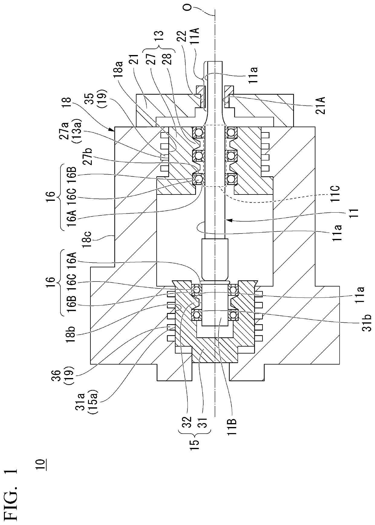
[0038]Referring to FIG. 1, a rotary machine 10 according to a first embodiment of the invention will be described. Note that O represented in FIG. 1 represents an axial line of a rotating element 11 (hereinafter, also referred to as an “axial line O”). FIG. 1 exemplifies a compressor as an example of the rotary machine 10. Also, FIG. 1 exemplifies a rotation shaft as an example of the rotating element 11.
[0039]The rotary machine 10 has the rotating element 11, bearing housings 13 and 15, a plurality of bearings 16, a casing 18, a temperature difference reducer 19, a support member 21, and a sealing member 22.
[0040]The rotating element 11 has a columnar shape and is disposed such that the rotation element 11 extends in a predetermined direction (an axial line O direction). The rotating element 11 has a tip end 11A, a base end 11B, and a bearing support portion 11C.
[0041]The tip end 11A is exposed from one end of the casing 18. The base end 11B is accommodated in the casing 18. The ba...
second embodiment
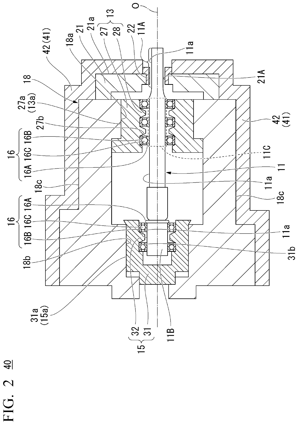
[0065]Referring to FIG. 2, a rotary machine 40 according to a second embodiment of the invention will be described. Note that in FIG. 2, the same reference numerals will be given to the same components as those in the structure body illustrated in FIG. 1.
[0066]The rotary machine is configured similarly to the rotary machine 10 according to the first embodiment other than the rotary machine 40 includes a temperature difference reducer 41 instead of the temperature difference reducer 19.
[0067]The temperature difference reducer 41 is configured to include a heat insulation material 42 covering an outer surface 18c of a casing 18 and an outer surface 21a of a support member 21.
[0068]As a heat insulation material 42, it is possible to use foam glass, glass wool, rock wool, calcium silicate, perlite, foam polystyrene, extruded foamed polystyrene, hard urethane foam, vinyl chloride foam, an insulation board, a sheathing board, an old newspaper heat insulation material, or the like.
[0069]Ac...
third embodiment
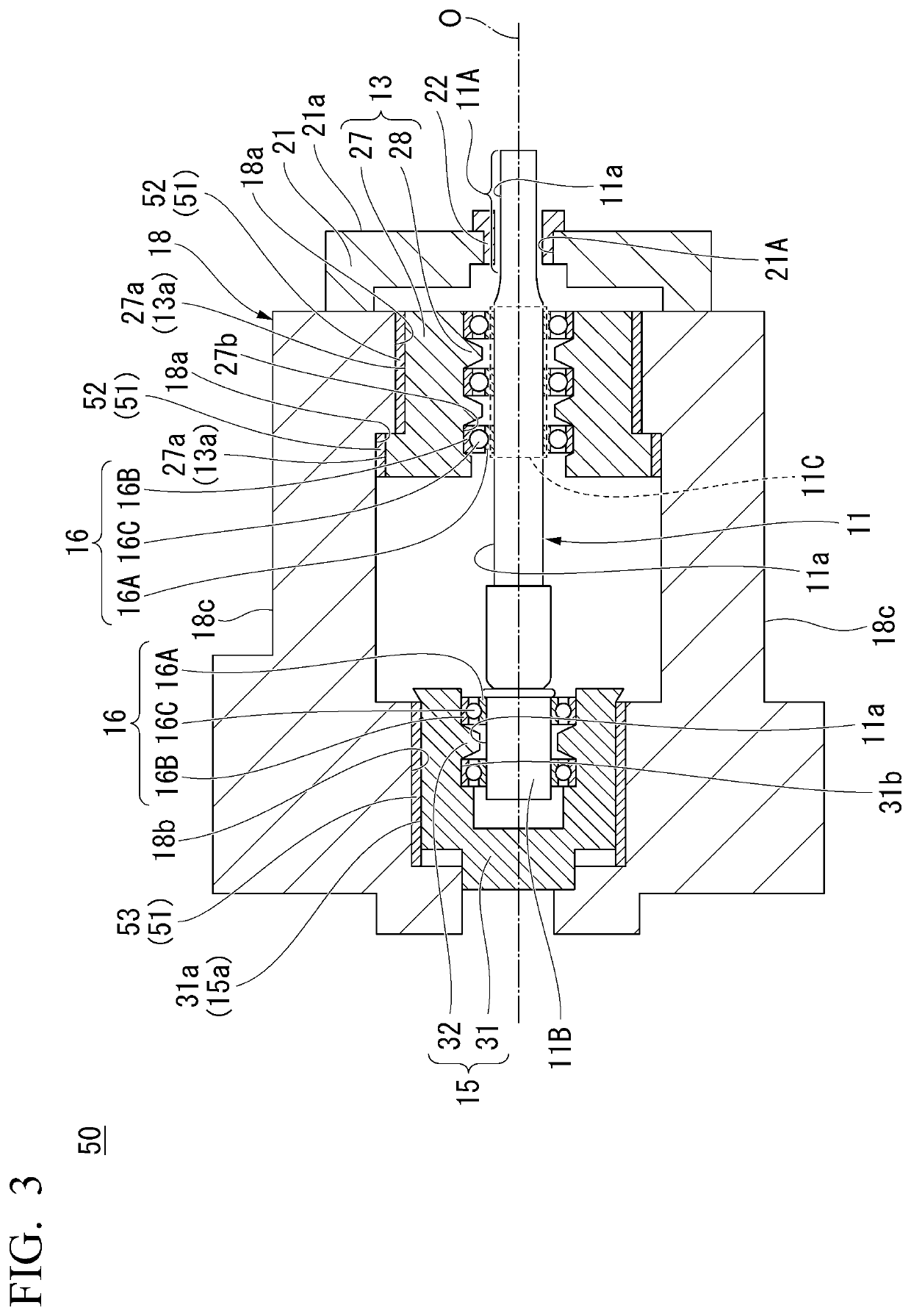
[0072]Referring to FIG. 3, a rotary machine 50 according to a third embodiment of the invention will be described. Note that in FIG. 3, the same reference numerals will be given to the same components of the structure body illustrated in FIG. 2.
[0073]The rotary machine 50 is configured similarly to the rotary machine 40 according to the second embodiment other than the rotary machine 50 has a temperature difference reducer 51 instead of the temperature difference reducer 41.
[0074]The temperature difference reducer 51 is configured to include low-heat conductivity members 52 and 53 with lower heat conductivity than that of a casing 18.
[0075]The low-heat conductivity member 52 is disposed between an outer peripheral surface 13a of a bearing housing 13 and an inner peripheral surface 18a of the casing 18. The low-heat conductivity member 53 is disposed between an outer peripheral surface 15a of a bearing housing 15 and an inner peripheral surface 18b of the casing 18.
[0076]As a materia...
PUM
 Abstract
Description
Claims
Application Information
 - R&D
- Intellectual Property
- Life Sciences
- Materials
- Tech Scout
- Unparalleled Data Quality
- Higher Quality Content
- 60% Fewer Hallucinations
Browse by: Latest US Patents, China's latest patents, Technical Efficacy Thesaurus, Application Domain, Technology Topic, Popular Technical Reports.
© 2025 PatSnap. All rights reserved.Legal|Privacy policy|Modern Slavery Act Transparency Statement|Sitemap|About US| Contact US: help@patsnap.com


