Multi-core electronic system

a multi-core, electronic system technology, applied in the field of multi-core electronic systems, can solve the problems of lack of integration between the on-chip bus technology and the dma technology, and achieve the effect of improving the work efficiency of the dma engine and speeding up communication

Active Publication Date: 2020-03-26
VIA TECH INC
View PDF6 Cites 0 Cited by
  • Summary
  • Abstract
  • Description
  • Claims
  • Application Information

AI Technical Summary

Benefits of technology

[0006]The disclosure provides an architecture of a multi-core electronic system, which may improve the work efficiency of a DMA engine configured on an on-chip ring bus architecture, and speed up communication between the DMA engine and each computing core in the multi-core electronic system.

Problems solved by technology

At present, there is a lack of integration between the on-chip bus technology and the DMA technology.

Method used


Image

  • Multi-core electronic system
  • Multi-core electronic system
  • Multi-core electronic system

Examples


first embodiment

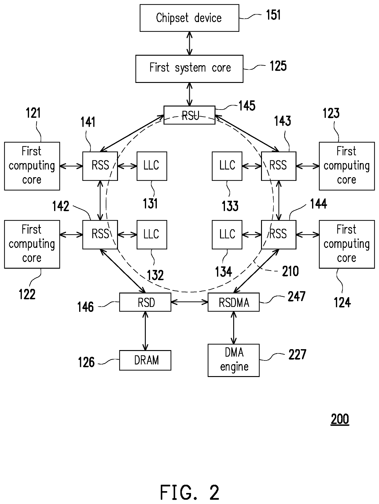
[0022]FIG. 2 is a schematic diagram of an architecture 200 of a multi-core electronic system according to the disclosure. The architecture 200 in FIG. 2 mainly includes a plurality of first computing cores 121 to 124, a first ring bus 210, a direct memory access (DMA) engine 227, and a DMA ring controller 247. In this embodiment, four first computing cores (121 to 124) are used as an example. Those who apply the embodiment may increase the number of computing cores based on actual requirements, and may even electrically connect more ring buses together (which will be described in the subsequent embodiment) for electrically connecting more computing cores. The first computing cores 121 to 124 are electrically connected to the first ring bus 210 through the first computing core ring controllers 141 to 144 respectively. The DMA ring controller 247 may also be referred to as a ring stop DMA module (RSDMA) 247 in this embodiment. The DMA ring controller 247 dedicated to the DMA engine 22...

third embodiment

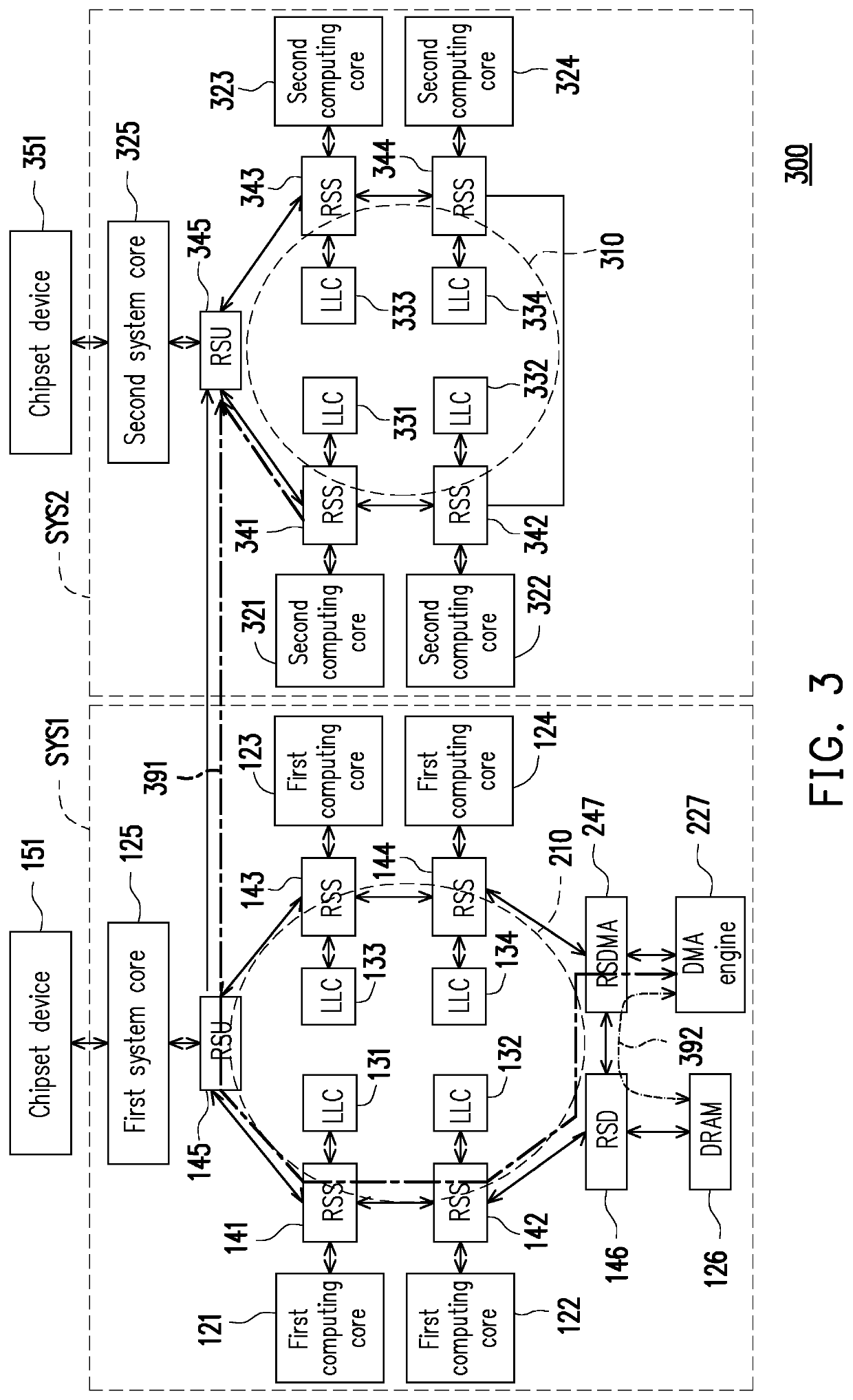
[0036]FIG. 4 is a schematic diagram of an architecture 400 of a multi-core electronic system according to the disclosure. The difference between FIG. 3 and FIG. 4 is that, in addition to the original ring stops and the corresponding components, the second ring bus 310 of FIG. 4 further includes a second DRAM 426 and a second DRAM ring controller (ring stop RSD) 446. The second DRAM 426 is electrically connected to the second ring bus 310 by the ring stop RSD 446. Accordingly, based on the fact that the first ring bus 210 and the second ring bus 310 are electrically connected to each other, the DMA engine 227 in the first ring bus 210 can perform the memory operation for the second DRAM 426.

[0037]In summary, according to the architecture of the multi-core electrical system provided in the embodiments of the disclosure, the DMA engine is configured to the ring bus through the DMA ring controller. The DMA ring controller for allowing the DMA engine to access data on the ring bus is add...


PUM


Abstract

An architecture of a multi-core electronic system is provided. The architecture includes a plurality of first computing cores, a first ring bus, a direct memory access (DMA) engine, and a DMA ring controller. The first computing cores are connected to the first ring bus. The DMA ring controller connects the DMA engine to the first ring bus. The first computing cores communicate with the DMA engine through the first ring bus and make the DMA engine perform a memory operation.

Description

CROSS-REFERENCE TO RELATED APPLICATION[0001]This application claims the priority benefit of Taiwan application serial no. 107133255, filed on Sep. 20, 2018. The entirety of the above-mentioned patent application is hereby incorporated by reference herein and made a part of this specification.BACKGROUND OF THE DISCLOSURE1. Field of the Disclosure[0002]The disclosure relates to a multi-core system, and more particularly, relates to a multi-core electronic system provided with a direct memory access (DMA) engine.2. Description of Related Art[0003]Currently, mainstream central processing units (CPUs) are usually adapted with multiple computing cores. In order to exchange information between these computing cores at high transfer speed, many types of on-chip buses have been developed to deliver serial communication among these computing cores. Ring bus is one of the on-chip buses commonly used in CPUs to allow these computing cores to pass data between each other using a variety of ring ...

Claims


Application Information

Patent Timeline
Patent Type & Authority Applications(United States)
IPC IPC(8): G06F13/28G06F13/40G06F15/78
CPCG06F15/7807G06F15/7839G06F13/40G06F13/28G06F15/17375
Inventor CHIANG, WEN-PIN
Owner VIA TECH INC
Why Eureka
Try Eureka