Method and apparatus for estimating internal state of thermal component

Active Publication Date: 2020-04-02
MITSUBISHI HEAVY IND LTD
0 Cites 2 Cited by

AI-Extracted Technical Summary

Problems solved by technology

A problem of the traditional method using the finite element method includes an increase in number of trials of finite element analysis having a high computation load with the number of parameters for tuning, which makes it difficult to respond to the case where immediacy is required.
During startup, flow in the turbine may form a spatially and temporally...

Benefits of technology

[0016]According to the present invention, the internal ...

Abstract

A method of estimating an internal state of a thermal component of the invention includes a measurement step of measuring state quantity of the thermal component, an analysis-condition creation step of creating an analysis condition, a data assimilation step of obtaining probability distribution of each temperature distribution and displacement distribution through data assimilation calculation using a contraction model, a measured value, and the analysis condition, a post-processing step of obtaining the internal state of the thermal component, an analysis step of obtaining solution vectors of the temperature distribution and the displacement distribution, and a contraction-model construction step of extracting a subspace characterizing a linear space of a vector set and constructing a contraction model using the subspace, wherein, in the data assimilation step, the probability distribution is calculated using the contraction model, and, in the analysis step and the contraction-model construction step, the contraction model is constructed.

Application Domain

Gas-turbine engine testingMachines/engines +5

Technology Topic

Data assimilationEngineering +3

Image

  • Method and apparatus for estimating internal state of thermal component
  • Method and apparatus for estimating internal state of thermal component
  • Method and apparatus for estimating internal state of thermal component

Examples

  • Experimental program(5)

Example

Embodiment 1
[0028]Embodiment 1 of the present invention exemplifies a turbine as a thermal component to which the present invention is applicable, and describes a basic idea to estimate thermal stress or a clearance that is an internal state of the thermal component.
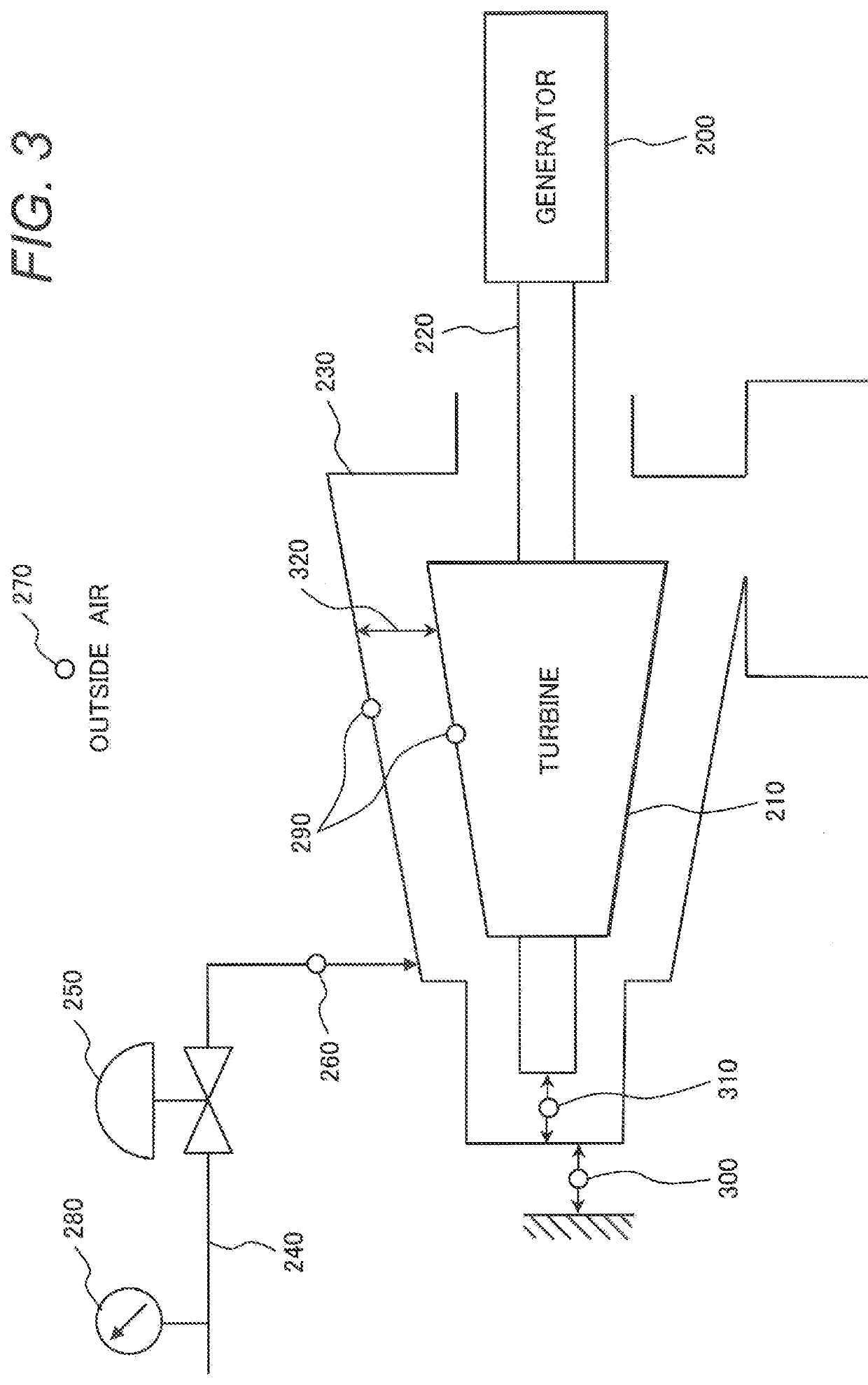
[0029]First, the thermal component, to which the present invention is applicable, is a turbine such as a vapor turbine or a gas turbine or a structure such as a boiler, and the turbine is now described while being illustrated in FIG. 3.
[0030]FIG. 3 shows an exemplary configuration of a power plant configured of a turbine and a generator. The power plant of FIG. 3 includes a generator 200, a turbine 210, a turbine rotor 220 connected to the turbine 210 and the generator 200, a turbine casing 230 accommodating the turbine, a piping 240 supplying a working fluid to the turbine, and a control valve 250 provided in the piping 240.
[0031]In such a power plant, a high-temperature, high-pressure fluid (vapor or gas) as the working fluid is introduced through the piping 240 into the turbine casing 230 to drive the turbine 210, and such driving force is transmitted to the generator 200 via the turbine rotor 220 for power generation. The working fluid (vapor or gas) that has worked in the turbine 210 is then exhausted to the outside.
[0032]In such a thermal composition into which the working fluid (vapor or gas) is introduced, thermal stress is known to internally occur in a specific state such as start-stop. In addition, a clearance, such as a clearance between the turbine casing 230 and the turbine 210, is supposed to be reduced due to thermal expansion of a metal of the structure.
[0033]Such an internal state such as the thermal stress or the clearance is an item that must be noted in controlling and monitoring in terms of a life of the thermal component, destruction of the thermal component structure, or efficiency of the thermal component. However, since the internal state cannot be directly measured, an internal or external state of the thermal component is typically monitored and measured to estimate the internal state, and the estimation results are reflected in control of the control valve 250 or monitored.
[0034]The exemplary power plant of FIG. 3 includes at least one each of a working fluid thermometer 260 to measure temperature of the working fluid, an outside-air temperature gauge 270 to measure outside-air temperature of the turbine 210, and a pressure gage 280 to measure working fluid temperature in order to estimate the internal state. The power plant further includes at least one metal thermometer 290 to measure metal temperature of each of the turbine rotor 220 and the casing. The power plant further includes at least one expansion indicator 300 to measure expansion of the casing or at least one differential-expansion indicator 310 to measure a clearance between the turbine rotor and the casing. It is natural that such measuring instruments, physical quantity to be measured, and a measurement position should be each appropriately selected in accordance with the thermal component to be monitored.
[0035]FIG. 1 is a view schematically illustrating a method and an apparatus for estimating an internal state of a thermal component according to the present invention. In FIG. 1, elements with reference signs 10, 20, 60, 90, and DB1 basically have the same configurations and functions as those of the measurement step 10, the analysis-condition creation step 20, the post-processing step 60, the thermal deformation analysis step 90 as the finite element analysis step, and the evaluation result database DB1, respectively, in the traditional technique of FIG. 2.
[0036]Embodiment 1 can be recognized to be given by adding a contraction-model construction step 40, a data assimilation step 50, a corrected analysis-condition database DB2, and a snapshot database DB3 to the configuration of the traditional technique of FIG. 2.
[0037]In the method and the apparatus for estimating the internal state of the thermal component of the present invention of FIG. 1, respective parts or steps generally have the following functions.
[0038]The measurement step 10 measures state quantity (temperature, expansion, and the like) of a structure or state quantity (temperature, pressure, and the like) of atmosphere in a power plant. In the example of the turbine of FIG. 3, various state quantities are measured by the working fluid thermometer 260, the outside-air temperature gauge 270, the pressure gage 280, the metal thermometer 290, the expansion indicator 300, and the differential-expansion indicator 310 to obtain measured values. In the analysis-condition creation step 20, an analysis condition of thermal deformation analysis is created.
[0039]In the data assimilation step 50, probability distribution of each of temperature distribution and displacement distribution and probability distribution of a corrected value of the analysis condition are obtained through data assimilation calculation using a contraction model given by dimensionally lowering a finite element model for the thermal deformation analysis and the measured value of the measurement step 10.
[0040]In the post-processing step 60, thermal stress of a portion, at which an inter-structure clearance, fatigue failure, or the like is a serious matter, and a corrected value of the analysis condition are obtained from the expected value of the probability distribution obtained in the data assimilation step 50, and are output into the evaluation result database DB1 and the corrected analysis-condition database DB2, respectively.
[0041]In the thermal deformation analysis step 90 being the finite element analysis step, solution vectors of the temperature distribution and the displacement distribution of the finite element model are obtained and output into the analysis result database (snapshot database DB3).
[0042]In the contraction-model construction step 40, a subspace characterizing a linear space defined by a vector set in the snapshot database DB3 is extracted and used to construct the contraction model.
[0043]The method and the apparatus for estimating the internal state of the thermal component of the present invention are configured as described above, so that a contraction model is constructed or reconstructed from a result of the analysis-condition creation step 20 and the corrected analysis-condition database DB2 by the thermal deformation analysis step 90 and the contraction-model construction step 40.
[0044]A first feature of the method and the apparatus, which each estimate the internal state of the thermal component according to Embodiment 1 of the present invention having the configuration of FIG. 1 as described above, is to use the contraction model given by dimensionally lowering a finite element equation as analysis means for data assimilation. This makes it possible to accelerate data assimilation calculation significantly compared with a case of directly using the finite element analysis.
[0045]A second feature of the method and the apparatus for estimating the internal state of the thermal component according to Embodiment 1 of the present invention is to have a contraction-model reconstruction step 100 to reconstruct a contraction model, i.e., a step of reconstructing a contraction model by expanding the snapshot database DB3 using the finite element analysis result at the condition stored in the corrected analysis-condition database DB2.
[0046]As the snapshot database DB3 contains a larger number of results similar to actually possible temperature distribution and displacement distribution of an objective structure, a more accurate contraction model can be produced. On the other hand, since the corrected analysis condition reflects a measurement result, thermal deformation analysis at a corrected analysis condition can be expected to contain temperature distribution and displacement distribution similar to actually possible temperature distribution and displacement distribution.
[0047]It is therefore possible to accurately evaluate thermal stress and thermal deformation by reconstructing the contraction model using the expanded snapshot database DB3.
[0048]The present invention makes it possible to accurately evaluate thermal stress and thermal deformation of a structure having a complicated shape within a practical time period. When measurement results before a certain time (initial time) are given, and when thermal deformation and thermal stress after the certain time are to be predicted, the present invention can be used as means for obtaining a structure temperature distribution at the initial time.
[0049]When an apparatus shown in FIG. 1 is configured, the apparatus is preferably configured such that the contraction-model reconstruction step 100 is provided on a center, steps of other portions are provided on a power plant side as an actual site, and communication can be performed between the center and the actual site via a communication facility. Consequently, the center can manage various data in a plurality of power plants in one place, and thus efficient operation is allowed while reflecting past operation performances in various power plants in design of a new power plant, for example. On the power plant side being the actual site, an apparatus configuration of the power plant can be simplified, and high-speed processing can be performed.
[0050]In summary, the present invention as described above is configured to be “a method of estimating an internal state of a thermal component, which is characterized by having a measurement step 10 of measuring state quantity of the thermal component, an analysis-condition creation step 20 of creating an analysis condition for analyzing the internal state of the thermal component, a data assimilation step 50 of obtaining probability distribution of each of temperature distribution and displacement distribution of the inside of the thermal component through data assimilation calculation using a contraction model given by dimensionally lowering a finite element model for the internal state analysis of the thermal component, a measured value of the measurement step 10, and the analysis condition, a post-processing step 60 of obtaining the internal state of the thermal component from an expected value of the probability distribution obtained in the data assimilation step 50, an analysis step 90 of obtaining solution vectors of the temperature distribution and the displacement distribution of the finite element model, and a contraction-model construction step 40 of extracting a subspace characterizing a linear space defined by a vector set of the temperature distribution and the displacement distribution and constructing a contraction model from the finite element model using the subspace, where the data assimilation step 50 calculates the probability distribution using the contraction model in the contraction-model construction step 40, and the analysis step 90 and the contraction-model construction step 40 construct or reconstruct the contraction model using the result of the analysis-condition creation step 20.”
[0051]The present invention is further configured to be “a method of estimating the internal state of the thermal component, which is characterized in that the data assimilation step 50 further obtains probability distribution of a corrected value of the analysis condition, the post-processing step 60 further obtains the corrected value of the analysis condition, and the analysis step 90 and the contraction-model construction step 40 reconstruct a contraction model using the corrected value from the post-processing step 60”.

Example

Embodiment 2
[0052]In Embodiment 2, the configuration described in Embodiment 1 is specifically described in more detail. FIG. 4 is a view illustrating a method and an apparatus for estimating the internal state of the thermal component according to Embodiment 2.
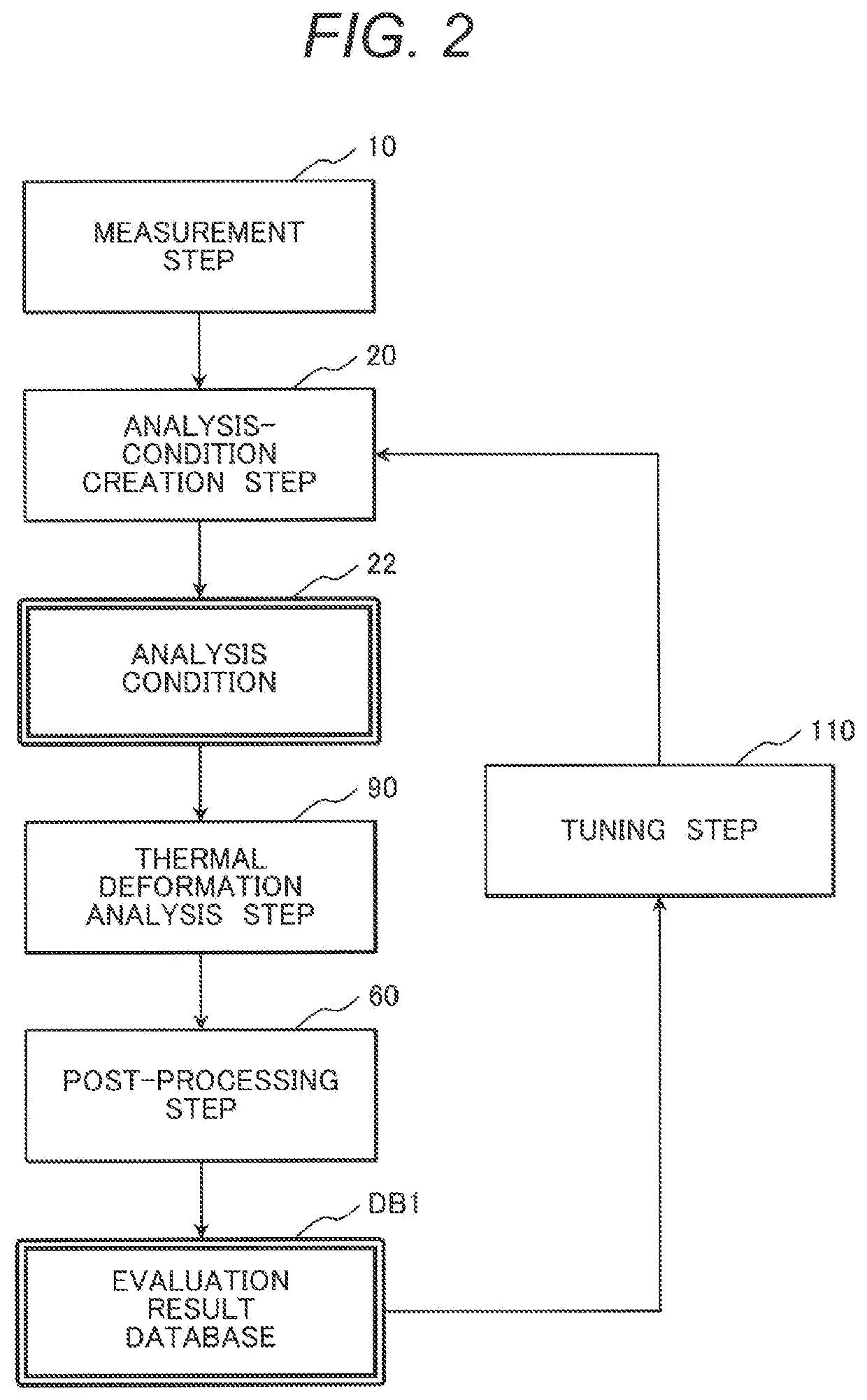
[0053]To compare the detailed configuration and functions of Embodiment 2 to those of the traditional technique of FIG. 2, Embodiment 2 of FIG. 4 can be recognized such that a step corresponding to the tuning 110 of the traditional method of FIG. 2 is modified into the data assimilation step 50, and a metal-surface heat-transfer-rate condition is directly identified in the data assimilation step 50 to address the above-described problems (inaccurate prediction of time evolution of temperature distribution, and insufficient clearance evaluation accuracy).
[0054]Furthermore, Embodiment 2 uses a contraction model for the data assimilation calculation, so that evaluation time can be advantageously extremely reduced compared with the traditional method 1 directly using the finite element analysis.
[0055]Furthermore, Embodiment 2 introduces a mechanism (the contraction-model reconstruction step 100) of sequentially improving accuracy of a contraction model using measurement data as a mechanism of compensating a reduction in evaluation accuracy by using the contraction model.
[0056]Through the above configuration, Embodiment 2 can more accurately evaluate the clearance within a practical time than the traditional method 1.
[0057]The method and the apparatus for estimating the internal state of the thermal component of Embodiment 2 shown in FIG. 4 shows a method for evaluating a clearance 320, which is a clearance between the turbine 210 and the casing during startup operation, as an internal state using the measurement results of temperature, expansion, and differential expansion, and the like.
[0058]The measurement step 10 in FIG. 4 receives time-series data of working fluid temperature, working fluid pressure, outside-air temperature, metal temperature, expansion, and differential expansion from the measuring instruments 260, 270, 280, 290, 300, and 310, and outputs measurement results 12 while transmitting the measurement results 12 to the analysis-condition creation step 20.
[0059]The analysis-condition creation step 20 creates the analysis conditions 22 such as a metal-surface heat-transfer-rate 23, ambient (working fluid, outside air) temperature 24 in the vicinity of the metal, and wall surface pressure 25 required for performing thermal deformation analysis of a metal portion such as a turbine, a turbine rotor, and a casing based on the measured values obtained in the measurement step 10. For example, mass transport or heat transport of the working fluid during startup, heat transfer of the metal portion, heat transfer between the working fluid and the metal portion are simulated by fluid/heat transfer circuit network analysis, thereby such analysis conditions can be calculated.
[0060]The analysis conditions 22 (metal-surface heat-transfer-rate 23, ambient (working fluid, outside air) temperature 24 in the vicinity of the metal, and wall surface pressure 25) obtained in the analysis-condition creation step 20 are given to the contraction-model reconstruction step 100. Corrected analysis conditions (identification parameter 82, preset parameter 83) stored in the corrected analysis-condition database DB2 are given to the contraction-model reconstruction step 100.
[0061]The contraction-model reconstruction step 100 beforehand has a heat-transfer contraction model 42 and a structure contraction model 43, and reconstructs a contraction model based on the input analysis conditions 22 and the corrected analysis condition.
[0062]In the contraction-model reconstruction step 100, first, finite element analysis is performed using the analysis conditions 22 in the thermal deformation analysis step 90 as a finite element analysis step to obtain temperature distribution and deformation distribution of the metal portion. The data obtained as a processing result of the thermal deformation analysis step 90 is stored in the snapshot database DB3.
[0063]The snapshot database DB3 stores a date set of a node temperature vector 32 as a result of obtaining time evolution of temperature distribution of the metal portion during startup by a finite element method, and a node displacement vector 33 as a result of obtaining thermal deformation of metal due to temperature distribution of the node temperature vector 32 by a finite element method.
[0064]The analysis conditions 22 (metal-surface heat-transfer-rate 23, ambient (working fluid, outside air) temperature 24 in the vicinity of the metal, the wall surface pressure 25) obtained in the analysis-condition creation step 20, or corrected analysis conditions (identification parameter 82, preset parameter 83) as described later from the corrected analysis-condition database DB2 are used as analysis conditions for the finite element method in the thermal deformation analysis step 90.
[0065]The contraction-model construction step 40 extracts a subspace characterizing a linear space defined by the temperature distribution given by the node temperature vector 32 in the snapshot database DB3, and produces the heat-transfer contraction model 42 from a finite element equation, which is given by discretizing a dominant equation of a heat transfer phenomenon of a metal portion, by Galerkin projection onto the subspace. Furthermore, the contraction-model construction step 40 extracts a subspace characterizing a linear space defined by the displacement distribution (vector) given by the node displacement vector 33 in the snapshot database DB3, and produces the structure contraction model 43 from a finite element equation, which is given by discretizing a dominant equation of thermal deformation, by Galerkin projection onto the subspace. This makes it possible to produce the simple contraction model 42 or 43, in which a finite element equation is represented by about 50 to 100 unknown variables and equations, while the finite element equation is represented by about one million unknown variables and equations, for example.
[0066]In FIG. 4, the data assimilation step 50 receives the measurement results 12 (time-series data of working fluid temperature, working fluid pressure, outside-air temperature, metal temperature, expansion, and differential expansion) of the power plant, and the analysis conditions 22 (the metal-surface heat-transfer-rate 23, the ambient (working fluid, outside air) temperature 24 in the vicinity of the metal, the wall surface pressure 25), and the contraction models (heat-transfer contraction model 42, structure contraction model 43) obtained in the contraction-model construction step 40, and uses state space models including the contraction models 42 and 43 to obtain time evolution of a state variable (probability distribution) containing an identification parameter 82 (model variable 42A determining the temperature distribution in the heat-transfer contraction model 42, model variable 43A determining the displacement distribution in the structure contraction model 43, and a metal-surface heat-transfer-rate condition 23A to be intentionally identified from the measured values in metal-surface heat-transfer-rate conditions 23) by a particle filter method. The heat-transfer-rate condition 23A of the identification parameter 82 is treated as a state variable having a random-walk-type time evaluation process to allow identification from the measured values.
[0067]In the following description, a condition to be preset for data assimilation, i.e., a heat-transfer-rate condition 23B corresponding to the metal-surface heat-transfer-rate conditions 23 excluding the condition 23A, the ambient (working fluid, outside air) temperature 24 in the vicinity of the metal, and the wall surface pressure 25 are each defined as the preset parameter 83.
[0068]The identification parameter 82 and the preset parameter 83 obtained in the data assimilation step 50 are finally stored in the corrected analysis-condition database DB2 after performing the following post-processing step 60, and used in the subsequent contraction model reconstruction processing.
[0069]In the particle filter method performed by the data assimilation step 50, probability distribution of the state variable is defined by a set of particles each having a specific state variable value, and then time evolution of the probability distribution is obtained through repetition of the following processing steps S1a to S1d. For the preset parameter 83, results of the analysis conditions 22 are allocated to all the particles.
[0070]In the processing step S1a, time evolution calculation is performed at a predetermined interval on each particle using the state space models.
[0071]In the processing step S1b, values of measurement instruments (260, 270, 280, 290, 300, 310) are evaluated from state valuable values of the particles, and values of the matching degree (likelihood) with measured values at the same time are calculated.
[0072]In the processing step S1c, the number of particles is assumed to be N, and N particles are selected and duplicated from among a particle set while repetition is permitted, and an original particle set is replaced with the duplicated particle set. A larger number of particles are selected with a higher likelihood. This allows a particle closer to a measured value to survive, leading to a result reflecting a measurement result.
[0073]The processing step S1d returns to the processing step S1a.
[0074]Time evolutions of the state variables (probability distributions represented by particle sets) including 42A and 43A as the model variables corrected with the measurement results and the identification parameter 82 are obtained through the above processing steps S1a to S1d.
[0075]In the post-processing step 60, an expected value of the probability distribution of the model variable 43A is substituted for a beforehand derived relational expression of the model variable 43A and a clearance of each portion to obtain a temporal variation in the clearance during startup, and the obtained results are output into the evaluation result database DB1. Furthermore, the corrected analysis condition including the expected value of the identification parameter 82 and the preset parameter 83 is output into the corrected analysis-condition database DB2.
[0076]Although Embodiment 2 illustrated in FIG. 4 has been exemplified on turbine startup, the present invention can be similarly applied to any load variation operation including stop operation.
[0077]In a modified configuration of Embodiment 2, processes on a series of the measurement step 10, the analysis-condition creation step 20, the data assimilation step 50, and the post-processing step 60 are linked to one another, thereby the clearance can be evaluated in real time.
[0078]Since contraction model analysis and data assimilation is easily calculated at high speed by GPGPU (general-purpose computing on graphics processing units), a configuration using a GPU machine in the data assimilation step 50 is considered as an apparatus configuration being a modified configuration of Embodiment 2.
[0079]In a possible thermal-stress evaluation method as another modified configuration of Embodiment 2, thermal stress necessary for heat cycle fatigue evaluation is obtained from an expected value of displacement distribution (probability distribution) in the post-processing step 60.
[0080]High-speed startup or flexible operation of a steam turbine is demanded for the necessity of efficient operation of the steam turbine under environment of introduction of a large amount of regenerated energy. On the other hand, high-speed startup or flexible operation increases the amount of thermal deformation caused by an increase in temperature difference in the metal portion, which causes a reduction in clearance, leading to an increase in possibility of contact of a rotation restraint part. This leads to a demand for a technique for accurately evaluating the clearance during load variation, and a demand for a technique for evaluating the clearance in real time.
[0081]A specific effect of Embodiment 2 includes that even if an inaccurate model to predict the heat transfer rate is obtained in the analysis-condition creation step 20, since the heat transfer rate can be corrected by data assimilation calculation, heat transfer/thermal deformation analysis of the metal portion can be performed more accurately. This effect allows accurate clearance evaluation results to be obtained.

Example

Embodiment 3
[0082]In Embodiment 3, a specific example of the contraction-model construction step 40 to construct the contraction model is described using numerical expressions with the method in Embodiment 2 to evaluate the clearance 320 during startup operation using the measurement results of temperature, expansion, differential expansion, and the like.
[0083]First, the following processing steps S2a to S2c are performed for a method for constructing the heat-transfer contraction model 42.
[0084]In the processing step S2a, a snapshot matrix of expression (1) is first constructed.
S1=[X11, . . . ,X1nb_cols_S1]  (1)
[0085]In the expression (1), (nb_cols_S1) is the number of node temperature vectors 32 extracted from the snapshot database DB3, X1i is a d dimensional node temperature vector in the snapshot database DB3, and S1 is a d1×nb_cols_S1 snapshot matrix.
[0086]For example, the d1×nb_cols_S1 snapshot matrix S1 (expression (1)), in which a plurality of (nb_cols_S1) d1 dimensional node temperature vectors 32 (represented by X1 in the expression) are extracted from the snapshot database DB3, and the node temperature vectors are arranged in columns, is constructed.
[0087]Subsequently, in the processing step S2a, the expression (1) is approximated by expression (2).
S1=U1·Σ1·W1T (2)
[0088]In the expression (2), U1 is a d1×r1 matrix in which left singular value vectors are arranged in columns, W1 is a d1×r1 matrix in which right singular value vectors are arranged in columns, and Σ1 is a r1×r1 matrix having singular values as diagonal components.
[0089]For example, the r1th singular value in descending order is obtained by truncated singular value decomposition of the snapshot matrix S1, and the snapshot matrix S1 in the expression (1) is approximated as shown in the expression (2) by a matrix product of the matrix U1 in which the left singular value vectors are arranged in columns, the r1×r1 matrix Σ1 in which the singular values are arranged as diagonal components, and the matrix W1 in which the right singular value vectors are arranged in columns. As a result, each column of the matrix U1 becomes a base vector of a subspace characterizing the linear space defined by a set of the node temperature vectors 32 (X1).
[0090]In the processing step S2b, an r1 dimensional contraction temperature vector φ1 of expression (3) is defined by a product of a transposed matrix of the matrix U1 and the node temperature vector 32 (X1).
ϕ1=U1T·X1  (3)
[0091]In the processing step S2c, a d1 dimensional simultaneous linear ordinary differential equation, in which the unknown variable is the node temperature vector 32 (X1) obtained through finite element approximation of a spatial term of a transient heat transfer equation, is dimensionally lowered by Galerkin projection to derive a heat-transfer contraction model expression.
[0092]First, the d1 dimensional simultaneous linear ordinary differential equation with the node temperature vector 32 (X1) as the unknown variable can be represented as shown in expression (4).
M 11 dX 1 dt + ( M 12 + ∑ f = 1 nb _ surfaces _ HTC h f M 13 f ) X 1 = ∑ f = 1 nb _ surfaces _ HTC h f TG f B 13 f ( 4 )
[0093]In the expression (4), (nb_surface_HTC) is the number of metal surface portions at each of which a heat transfer condition is set, X1 is a d1 dimensional node temperature vector 32, hf is a heat transfer coefficient of each surface, TGf is ambient temperature 24 of each surface, M11 is a d1×d1 matrix on discretization of a heat capacity term, M12 is a d1×d1 matrix on discretization of a heat transfer term, and M13f and B13f are a d1×d1 matrix and a d1 dimensional vector, respectively, on discretization of a heat transfer term for a surface f.
[0094]Furthermore, to derive a dimensionally lowered heat-transfer contraction model expression from the expression (4), the unknown variable X1 in the expression (4) is replaced with the contraction temperature vector φ1 by the relational expression of the expression (3), and the right side and the left side of the expression (4) are each multiplied by the transposed matrix of U1. This makes it possible to obtain a heat-transfer contraction model expression of expression (5) being a low dimensional (r1) simultaneous linear ordinary differential equation with the contraction temperature vector φ1 as an unknown variable.
M 11 R d φ 1 dt + ( M 12 R + ∑ f = 1 nb _ surfaces _ HTC h f M 13 R f ) φ 1 = ∑ f = 1 nb _ surfaces _ HTC h f TG f B 13 R f ( 5 )
[0095]In the expression (5), M11R, M12R, M13Rf, and B13Rf are calculated by the following expressions (6), (7), (8), and (9), respectively.
M11R=U1T·M11·U1  (6)
M12R=U1T·M12·U1  (7)
M13Rf=U1T·M13f·U1  (8)
B13Rf=U1T·B13f (9)
[0096]These are the method of constructing the heat-transfer contraction model 42 in the contraction-model construction step of FIG. 4. Subsequently, description is made on the following processing steps S3a to S3c as a method of constructing the structure contraction model 43 in the contraction-model construction step of FIG. 4. The processing steps S2a to S2c and the processing steps S3a to S3c essentially perform the same processing while data to be treated is partially different (for example, the node temperature vector 32 in the former, and the node displacement vector 33 in the latter).
[0097]In the processing step S3a, a snapshot matrix of expression (10) is first constructed.
S2=[X21, . . . ,X2nb_cols_S2]  (10)
[0098]In the expression (10), (nb_cols_S2) is the number of node displacement vectors 33 extracted from the snapshot database DB3, X2i is a d2 dimensional node displacement vector in the snapshot database DB3, and S2 is a d2×nb_cols_S2 snapshot matrix.
[0099]For example, the d2×nb_cols_S2 snapshot matrix S2 (expression (10)), in which a plurality of (nb_cols_S2) d2 dimensional node displacement vectors 33 (represented by X2 in the expression) are extracted from the snapshot database DB3, and the node displacement vectors are arranged in columns, is constructed.
[0100]Subsequently, in the processing step S3a, the expression (10) is approximated by expression (11).
S2=U2·Σ2·W2T (11)
[0101]In the expression (11), U2 is a d2×r2 matrix in which left singular value vectors are arranged in columns, W2 is a d2×r2 matrix in which right singular value vectors are arranged in columns, and Σ2 is a r2×r2 matrix having singular values as diagonal components.
[0102]For example, r2 number of singular values in descending order are obtained by truncated singular value decomposition of the snapshot matrix S2, and the snapshot matrix S2 in the expression (10) is approximated as shown in the expression (11) by a matrix product of the matrix U2 in which left singular value vectors are arranged in columns, the r2×r2 matrix Σ2 in which singular values are arranged as diagonal components, and the matrix W2 in which right singular value vectors are arranged in columns. As a result, each column of the matrix U2 becomes a base vector of a subspace characterizing the linear space defined by a set of the node displacement vectors 33 (X2).
[0103]In the processing step S3b, an r2 dimensional contraction displacement vector φ2 of expression (12) is defined by a product of a transposed matrix of the matrix U2 and the node displacement vector 33 (X2).
ϕ2=U2T·X2  (12)
[0104]In the processing step S3c, a d2 dimensional simultaneous linear equation, in which the unknown variable is the node displacement vector 33 (X2) obtained through finite element approximation of a structural equation containing a thermal stress term, is dimensionally lowered by Galerkin projection to derive a structure contraction model expression.
[0105]The d2 dimensional simultaneous linear equation with the node displacement vector 33 (X2) as the unknown variable can be represented as shown in expression (13).
M 21 X 2 = ∑ f = 1 nb _ surfaces _ P P f B 22 f + M 23 ( X 1 - T 1 0 ) + B 24 ( 13 )
[0106]In the expression (13), (nb_surface_P) is the number of metal surface portions at each of which a pressure condition is set, X2 is a d2 dimensional node temperature vector 33, T1 is a d1 dimensional node temperature vector 32, T10 is a d1 dimensional node temperature vector providing reference temperature of thermal strain, pf is wall surface pressure 25 of each surface, M21 is a d2×d2 matrix on discretization of a stiffness term, M23 is a d2×d2 matrix on discretization of thermal stress, B22f is a d2 dimensional vector on discretization of pressure for a surface f, and B24 is a d2 dimensional vector on discretization of another external force such as gravity.
[0107]Furthermore, to derive a dimensionally lowered structure contraction model expression from the expression (12), the unknown variable X2 in the expression (13) is replaced with the contraction displacement vector φ2 by the relational expression of the expression (12), and the right side and the left side of the expression (13) are each multiplied by the transposed matrix of U2. This makes it possible to obtain a structure contraction model expression of expression (14) being a low dimensional (r2) simultaneous linear equation with the contraction displacement vector φ2 as an unknown variable. In the expression (14), the term of MR23(φ1-φ10) represents a thermal stress term modeled as a function of the contraction temperature vector. These are the method of constructing the structure contraction model.
M R 21 φ 2 = ∑ f = 1 nb _ surfaces _ P P f BR 22 f + M R 23 ( φ 1 - φ1 0 ) + BR 24 ( 14 )
[0108]In the expression (14), M21R, M23R, B22Rf, B24, and φ10 are calculated by the following expressions (15), (16), (17), (18), and (19), respectively.
M21R=U2T·M21·U2  (15)
M23R=U2T·M23·U2U2  (16)
B22Rf=U2T·B23U2  (17)
B24=U2T·B24  (18)
ϕ10=U1T·X10 (19)
[0109]In the construction of the heat-transfer contraction model 42 described in Embodiment 3, the finite element equation of the expression (4) is contracted from the high dimension (d1) to the low dimension (r1) expression (5) while a heat-transfer coefficient parameter is remained. It is therefore possible to investigate effect evaluation of the heat transfer coefficient using the heat-transfer contraction model. In particular, the expression (5) can be used as an alternative of the finite element equation of the expression (4) to identify the heat transfer coefficient in data assimilation calculation.
[0110]Similarly, in the construction of the structure contraction model 43, the finite element equation of the expression (13) is contracted from the high dimension (d2) to the low dimension (r2) expression (14) while a pressure parameter is remained. In particular, the thermal stress term is dimensionally lowered to the r2 dimension as a function of the contraction temperature vector. It is therefore possible to use the expression (14) as an alternative of the finite element equation of the expression (13) in data assimilation calculation.
[0111]Although lowering dimension of a finite element equation typically causes error for the finite element equation, when a large number of results similar to actually possible temperature distribution and displacement distribution are contained in the snapshot database DB3, contraction of d1r1 or d2r2 is possible while practical accuracy is maintained. In this case, since the expressions (4) and (13) being the finite element equations can be substituted by the expressions (5) and (14), respectively, being the contraction model expressions allowing high-speed calculation, the data assimilation calculation can be performed within a practical time period.
[0112]Using the contraction model of Embodiment 3 makes it possible to perform the data assimilation calculation within a practical time period.
[0113]In Embodiment 3, when material characteristics have temperature dependence, the matrix M11 involved in density and specific heat and the matrix M12 involved in thermal conductivity in the expression (4) are each a function of temperature. Similarly, the matrix M21 involved in Young's modulus and Poisson's ratio, the matrix M23 involved in a coefficient of thermal expansion, and the vector B24 involved in gravity (density) in the expression (13) are each a function of temperature. Even if the coefficient matrix is a function of temperature and the expressions (4) and (13) are each a nonlinear equation as described above, the heat-transfer contraction model expression and the structure contraction model expression can be easily constructed from the expressions (4) and (13), respectively, by a method called TPLM (Trajectory Piecewise Linear Method).
[0114]Furthermore, in Embodiment 3, when the metal portion has a high temperature, although influence of radiation needs to be considered, when a radiation phenomenon is modeled, a vector as the fourth power of each component of the node temperature vector appears in the expression (4). In such a case, the heat-transfer contraction model expression can be easily constructed from the expression (4) by a method called DEIM (Discrete Empirical Interpolation Method).

PUM

no PUM

Description & Claims & Application Information

We can also present the details of the Description, Claims and Application information to help users get a comprehensive understanding of the technical details of the patent, such as background art, summary of invention, brief description of drawings, description of embodiments, and other original content. On the other hand, users can also determine the specific scope of protection of the technology through the list of claims; as well as understand the changes in the life cycle of the technology with the presentation of the patent timeline. Login to view more.

Similar technology patents

Detection method for preventing automobile from colliding

InactiveUS20090171586A1reduce convergence timeaccurately estimate
Owner:NAT TAIWAN UNIV

Classification and recommendation of technical efficacy words

  • accurately estimate
  • simple technique

Manufacturing Process For Producing Narrow Sensors

InactiveUS20080135408A1simple technique
Owner:NOVO NORDISK AS

Construction set element

ActiveUS20210023469A1simple techniquecombinatorial capability thereof be increase
Owner:LLC TRADE HOUSE LYTAR UKRAINE

Method for producing chiral metal oxide structure, and chiral porous structure

InactiveUS20170275179A1simple technique
Owner:KANAGAWA UNIVERSITY

Meteorological station for real-time calculation of photovoltaic power station irradiation value

ActiveCN109462367AGood power generationsimple technique
Owner:SHANGHAI TAOKE NETWORK TECHN
Why Eureka
Try Eureka