Windage shield system for a gas turbine engine

a gas turbine engine and windage shield technology, which is applied in the direction of machines/engines, liquid fuel engines, mechanical equipment, etc., can solve the problems of difficult or impossible access to the rear plane of the fan disc at such positions

Inactive Publication Date: 2020-04-09
ROLLS ROYCE PLC
View PDF0 Cites 0 Cited by
  • Summary
  • Abstract
  • Description
  • Claims
  • Application Information

AI Technical Summary

Benefits of technology

[0005]By providing the functionality of windage shielding and rear-plane balancing within a single arrangement, the system allows for rear-plane balancing of a fan disc in cases where access to the downstream end of the fan disc of an engine is difficult or impossible, thus precluding the use of balancing weights.
[0013]According to an example, a method of forming a fan disc assembly for a gas turbine engine, the fan disc assembly comprising a fan disc and a windage shield, comprises the steps of mounting a windage shield system according to an example to the fan disc and adjusting the azimuthal positions of the centres of mass of the first and second elements with respect to the rotation axis of the fan disc such that the magnitude of the total unbalance of the fan disc assembly is less than the unbalance of the fan disc alone, and preferably such that the total unbalance of the fan disc assembly is minimised and more preferably equal to zero.

Problems solved by technology

In some gas turbine engines, for example certain geared turbofan engines, access to the rear plane of the fan disc at such positions may be difficult or impossible, and / or there may be no suitable locations for applying balancing weights to achieve rear plane balancing.

Method used


Image

  • Windage shield system for a gas turbine engine
  • Windage shield system for a gas turbine engine
  • Windage shield system for a gas turbine engine

Examples


Embodiment Construction

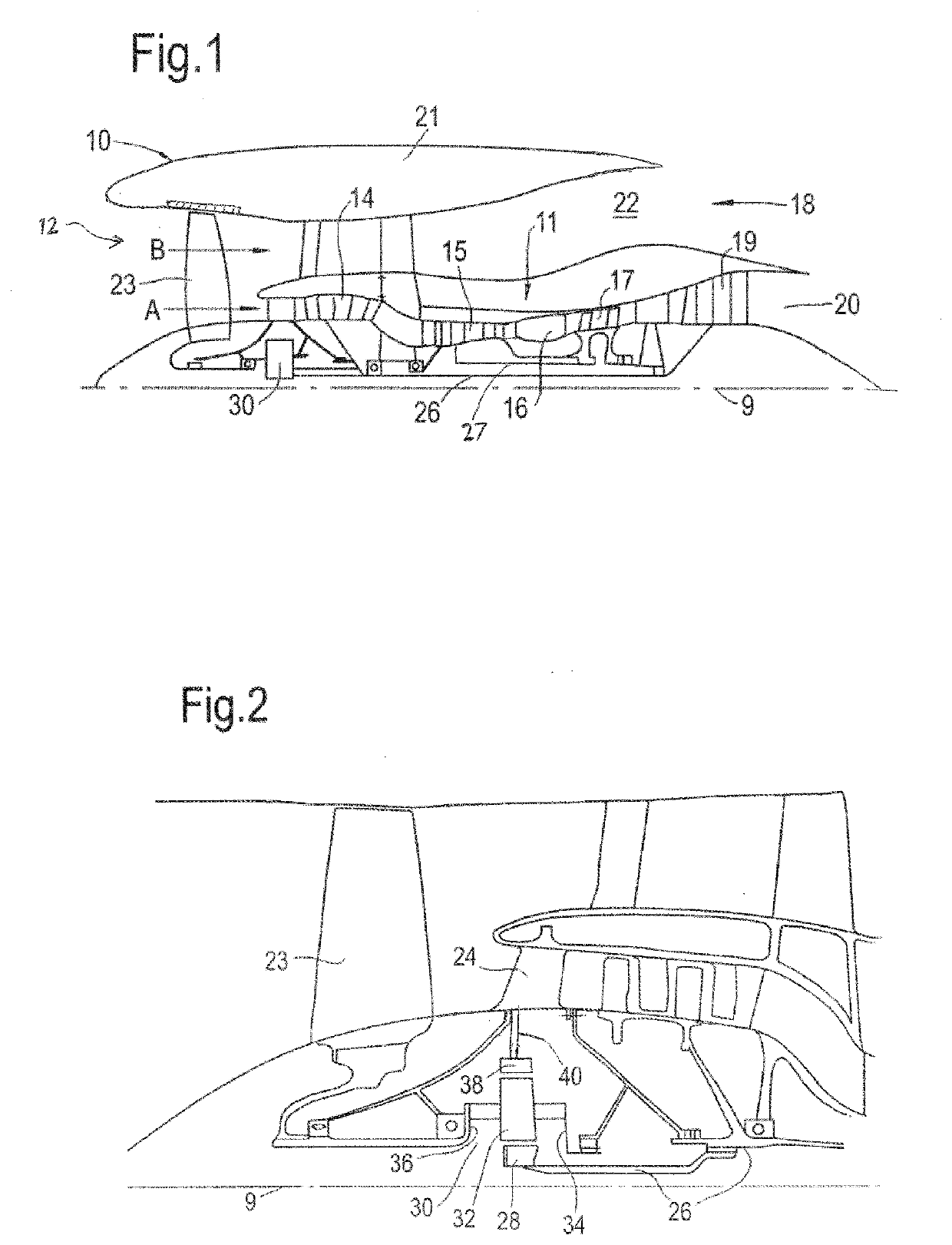
[0031]FIG. 1 illustrates a gas turbine engine 10 having a principal rotational axis 9. The engine 10 comprises an air intake 12 and a propulsive fan 23 that generates two airflows: a core airflow A and a bypass airflow B. The gas turbine engine 10 comprises a core 11 that receives the core airflow A. The engine core 11 comprises, in axial flow series, a low pressure compressor 14, a high-pressure compressor 15, combustion equipment 16, a high-pressure turbine 17, a low pressure turbine 19 and a core exhaust nozzle 20. A nacelle 21 surrounds the gas turbine engine 10 and defines a bypass duct 22 and a bypass exhaust nozzle 18. The bypass airflow B flows through the bypass duct 22. The fan 23 is attached to and driven by the low pressure turbine 19 via a shaft 26 and an epicyclic gearbox 30.

[0032]In use, the core airflow A is accelerated and compressed by the low pressure compressor 14 and directed into the high pressure compressor 15 where further compression takes place. The compres...


PUM


Abstract

A windage shield system comprises first and second hollow cylindrical elements, the longitudinal axes of the outer and inner surfaces of each element being parallel and mutually displaced. The elements are mounted to the downstream end of a fan disc such that the longitudinal axes of the inner surface of the first element and the outer surface of the second element coincide with the rotational axis of the disc. The centres of mass of the elements are mountable with azimuthal offsets ϕ1, ϕ2 with respect to the fan disc, each being selectable from a large number of values in the range 0° to 360°. The first element is integral with a windage shield. The system allows a fan disc to be provided with a windage shield and the resulting assembly to be balanced at its rear plane in cases where access to the rear of the fan disc is difficult.

Description

CROSS-REFERENCE TO RELATED PATENT APPLICATIONS[0001]This application is based upon and claims the benefit of priority from UK Patent Application No. GB1816260.2, filed on Oct. 5, 2018, the entire contents of which are incorporated herein by reference.BACKGROUNDTechnical Field[0002]Examples of windage shield systems for a gas turbine engine, such as a geared turbofan engine, are disclosed.Description of Related Art[0003]Balancing of the fan disc of a gas turbine engine is typically achieved by application of balancing weights at or near the front and rear planes of the fan disc at positions radially inward of the fan disc. In some gas turbine engines, for example certain geared turbofan engines, access to the rear plane of the fan disc at such positions may be difficult or impossible, and / or there may be no suitable locations for applying balancing weights to achieve rear plane balancing.SUMMARY[0004]According to an example, a windage shield system for a fan disc of a gas turbine eng...

Claims


Application Information

Patent Timeline
Patent Type & Authority Applications(United States)
IPC IPC(8): F01D5/02F04D29/66
CPCF04D29/662F05D2220/36F01D5/027F05D2260/15
Inventor BREEN, CLIVE
Owner ROLLS ROYCE PLC
Why Eureka
Try Eureka