
Surgical instrument

a surgical and end tool technology, applied in the field of surgical instruments, can solve the problems of inconvenient operation inability to access the surgical region and perform various surgical operations, and inability to intuitively compare the operation of the operator's end tool to the actual bending operation, so as to improve the convenience of the surgical operator, improve the accuracy, and improve the quickness of the surgical operation.

Active Publication Date: 2020-04-23
LIVSMED INC
View PDF0 Cites 5 Cited by
  • Summary
  • Abstract
  • Description
  • Claims
  • Application Information

AI Technical Summary

Benefits of technology

The invention makes it easier for a surgical operator to control the end tool, which leads to better operational accuracy, reliability, and speed. This is because the operation directions of the operator and the end tool are the same.

Problems solved by technology

However, open surgery, which cuts and opens the skin of a surgical region and cures, shapes, or removes an organ therein, may cause bleeding, side effects, pain, scars, or the like.
However, since a conventional surgical instrument uses an unbendable end tool, it is not suitable for accessing a surgical region and performing various surgical operations.
However, an operation of an operator for bending the end tool to perform a surgical operation is not intuitively identical to an actual bending operation of the end tool for performing the surgical operation.
Therefore, for surgical operators, it is difficult to perform an intuitive operation, and it takes a long time to learn how to use the surgical instrument.

Method used


Image

  • Surgical instrument
  • Surgical instrument
  • Surgical instrument

Examples


first embodiment

of Surgical Instrument

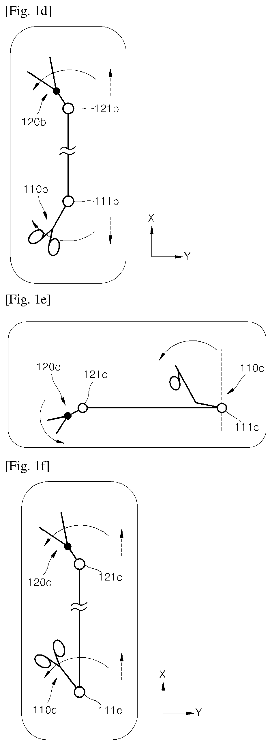
[0037]A surgical instrument according to the present invention is characterized in that, for at least any one of the pitch, yaw, and actuation operations, when an operator is rotated in any one direction, an end tool rotates in a direction that is intuitively identical to an operation direction of the operator.

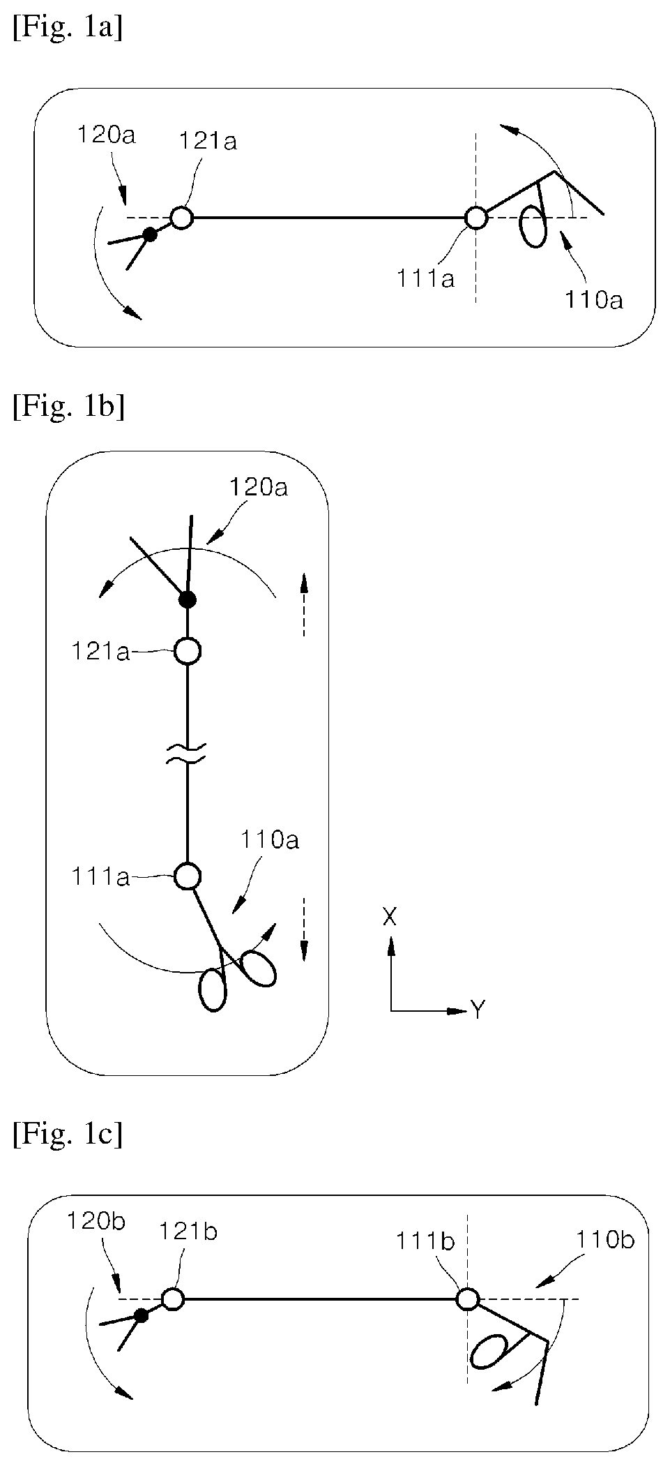
[0038]FIG. 1A is a schematic diagram illustrating a pitch operation of a conventional surgical instrument, and FIG. 1B is a schematic diagram illustrating a yaw operation thereof.

[0039]Referring to FIG. 1A, in order to perform a pitch operation of a conventional surgical instrument, in a state where an end tool 120a is formed in front of an end tool rotation center 121a and an operator 110a is formed in back of an operator rotation center 111a, when the operator 110a is rotated in a clockwise direction, the end tool 120a also rotates in the clockwise direction, and when the operator 110a is rotated in a counterclockwise direction, the end tool 120a also r...

second embodiment

of Surgical Instrument

[0152]Hereinafter, a surgical instrument 200 according to a second embodiment of the present invention will be described. The surgical instrument 200 according to the second embodiment of the present invention is different in terms the configuration of an operating force transmission assembly 235 from the surgical instrument 100 (see FIG. 2) according to the first embodiment of the present invention. This difference in the configuration from the first embodiment will be described later in detail.

[0153]FIG. 16 is a perspective view of a surgical instrument according to a second embodiment of the present invention, FIG. 17 is a plan view of the surgical instrument of FIG. 16, and FIG. 18 is a perspective view illustrating an operator of the surgical instrument of FIG. 16.

[0154]Referring to FIGS. 16, 17, and 18, the surgical instrument 200 according to the second embodiment of the present invention includes an operator 210, an end tool 220, an operating force tran...


PUM


Abstract

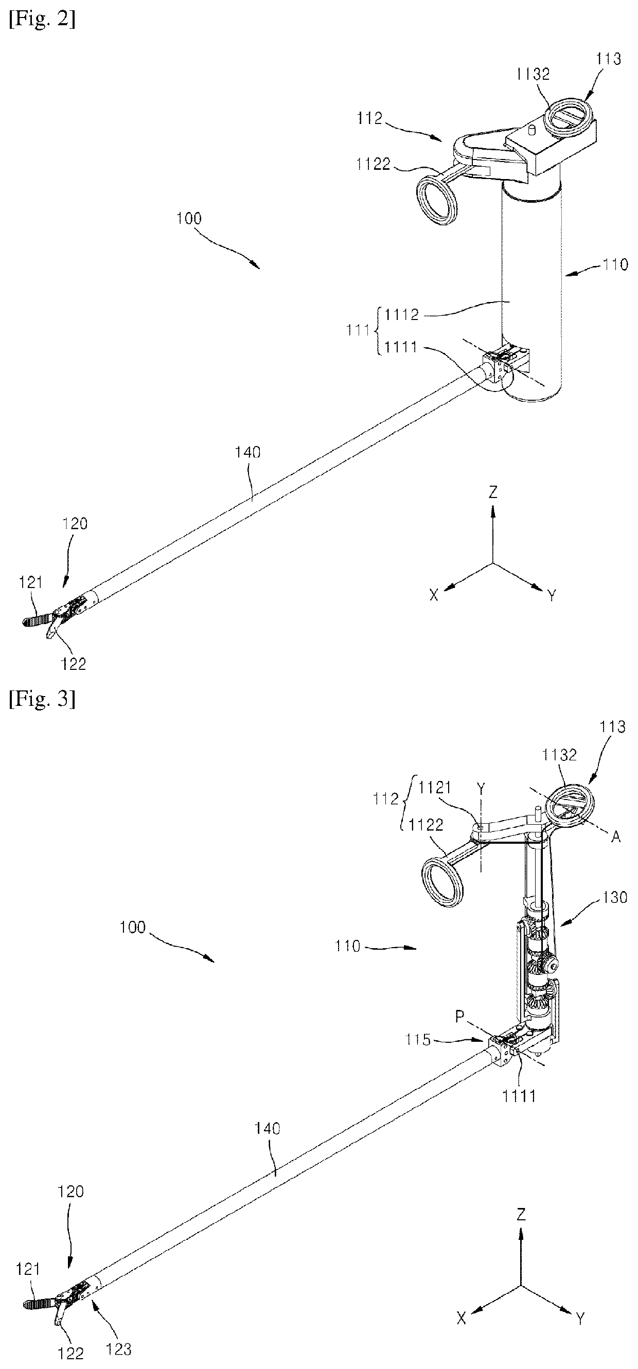
Provided is a surgical instrument including: an end tool including a first jaw and a second jaw configured to rotate independently; an operator including a pitch operator controlling a pitch motion of the end tool, a yaw operator controlling a yaw motion of the end tool, and an actuation operator controlling an actuation motion of the end tool; an operating force transmitter including a first jaw wire connected with the first jaw to transmit an operation of the operator to the first jaw, a second jaw wire connected with the second jaw to transmit an operation of the operator to the second jaw, and one or more differential members transmitting a rotation of the yaw operator or the actuation operator to the first jaw or the second jaw via the first jaw wire or the second jaw wire; and a connector configured to extend in a first direction (X axis) and having one end portion coupled to the end tool and the other end portion coupled to the operator to connect the operator and the end tool, wherein the pitch operator is configured to rotate around a second direction (Y axis) perpendicular to the first direction; and at least a portion of the operator is configured to be more adjacent to the end tool than a rotating axis of the operator in at least any one operation state of the operator.

Description

CROSS-REFERENCE TO RELATED APPLICATIONS[0001]This application is a divisional application of U.S. application Ser. No. 15 / 306,371 filed on Oct. 24, 2016, which is a national stage application under 35 USC § 371 of PCT / KR2014 / 009599 filed on Oct. 14, 2014, and claims priority to Korean patent application No. 10-2014-0049460 filed on Apr. 24, 2014, the disclosures of which are incorporated herein by reference in their entirety.TECHNICAL FIELD[0002]The present invention relates to surgical instruments, and more particularly, to surgical instruments that may be manually operated to perform laparoscopic operations or various surgical operations.BACKGROUND ART[0003]A surgical operation is an operation for curing a disease by cutting, incising, and processing skin, membranes, or other tissues by using medical instruments. However, open surgery, which cuts and opens the skin of a surgical region and cures, shapes, or removes an organ therein, may cause bleeding, side effects, pain, scars, o...

Claims


Application Information

Patent Timeline
Patent Type & Authority Applications(United States)
IPC IPC(8): A61B17/29A61B17/00A61B34/00
CPCA61B2017/2912A61B2017/2925A61B34/71A61B17/29A61B2017/2911A61B17/2909A61B2017/00323A61B2017/2927A61B2017/2923A61B17/00234F16H21/52
Inventor LEE, JUNG JOOKIM, HEE JINBACH, DU JIN
Owner LIVSMED INC
Learn More