Descan compensation in scanning lidar

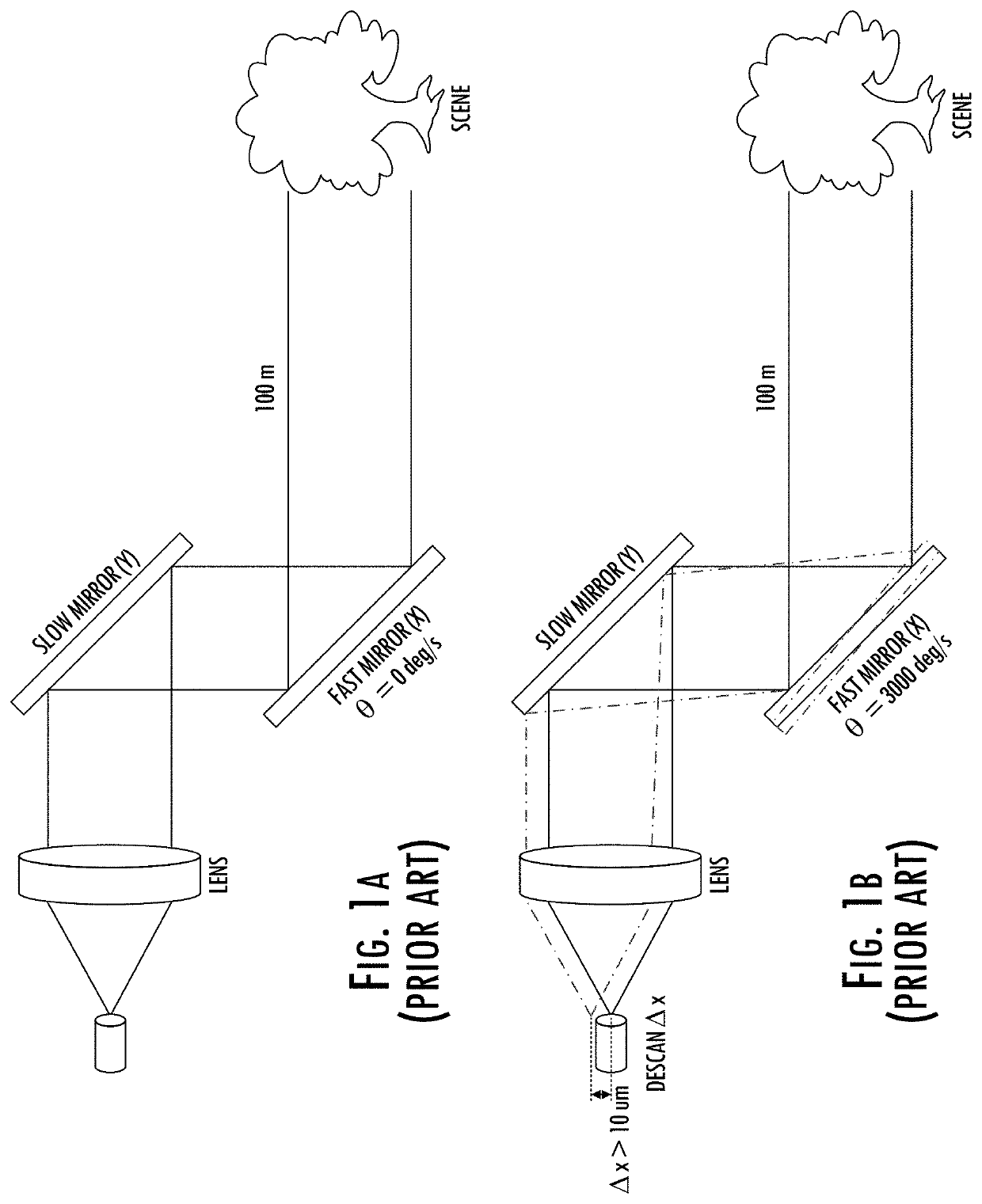
a lidar and compensation technology, applied in the field of descan compensation in scanning lidar, can solve the problems of reducing coupling efficiency, affecting the detection accuracy of lidar beams, and severely degrading the target signal of distant objects, so as to improve the range, framerate, or detection effect, and minimize optical losses

Active Publication Date: 2020-04-23
AEVA INC
View PDF4 Cites 15 Cited by
  • Summary
  • Abstract
  • Description
  • Claims
  • Application Information

AI Technical Summary

Benefits of technology

[0005]Example implementations of the present disclosure are configured to simultaneously measure the range and velocity, using coherent detection and having the added benefit of immunity to crosstalk from other LIDAR systems. Other implementations may be used with incoherent systems to improve, range, framerate, or detection. Example implementations minimize optical losses in the beam's return path, thereby increasing the system's measurement range. Additionally, by using nondegenerate laser sources, example implementations can leverage mature wavelength division multiplexing (WDM) techniques often used in integrated silicon photonics, a desired platform due to its compactness and relative stability in varying environmental conditions.
[0006]As described above, the decenter at the fiber tip upon return of the target signal is the primary source of degradation in coupling efficiency. Example implementations of the present disclosure mitigate the hampering effect of th...

Problems solved by technology

When using the mirrors with a high angular velocity (for example, faster than 3000 degrees per second) and single-mode fiber-based detection, the target signal from distant objects is severely degraded.
This slight angular change causes a walk-off of the target signal at the fiber tip decreasing the coupling efficiency, which manifests itself as a weaker signal detection.
Historically, FM LIDAR systems suffer from sign...

Method used


Image

  • Descan compensation in scanning lidar
  • Descan compensation in scanning lidar
  • Descan compensation in scanning lidar

Examples


Embodiment Construction

[0043]Some implementations of the present disclosure will now be described more fully hereinafter with reference to the accompanying figures, in which some, but not all implementations of the disclosure are shown. Indeed, various implementations of the disclosure may be embodied in many different forms and should not be construed as limited to the implementations set forth herein; rather, these example implementations are provided so that this disclosure will be thorough and complete, and will fully convey the scope of the disclosure to those skilled in the art. For example, reference may be made herein to quantitative measures, values, relationships or the like (e.g., planar, coplanar, perpendicular). Unless otherwise stated, any one or more if not all of these may be absolute or approximate to account for acceptable variations that may occur, such as those due to engineering tolerances or the like. Like reference numerals refer to like elements throughout.

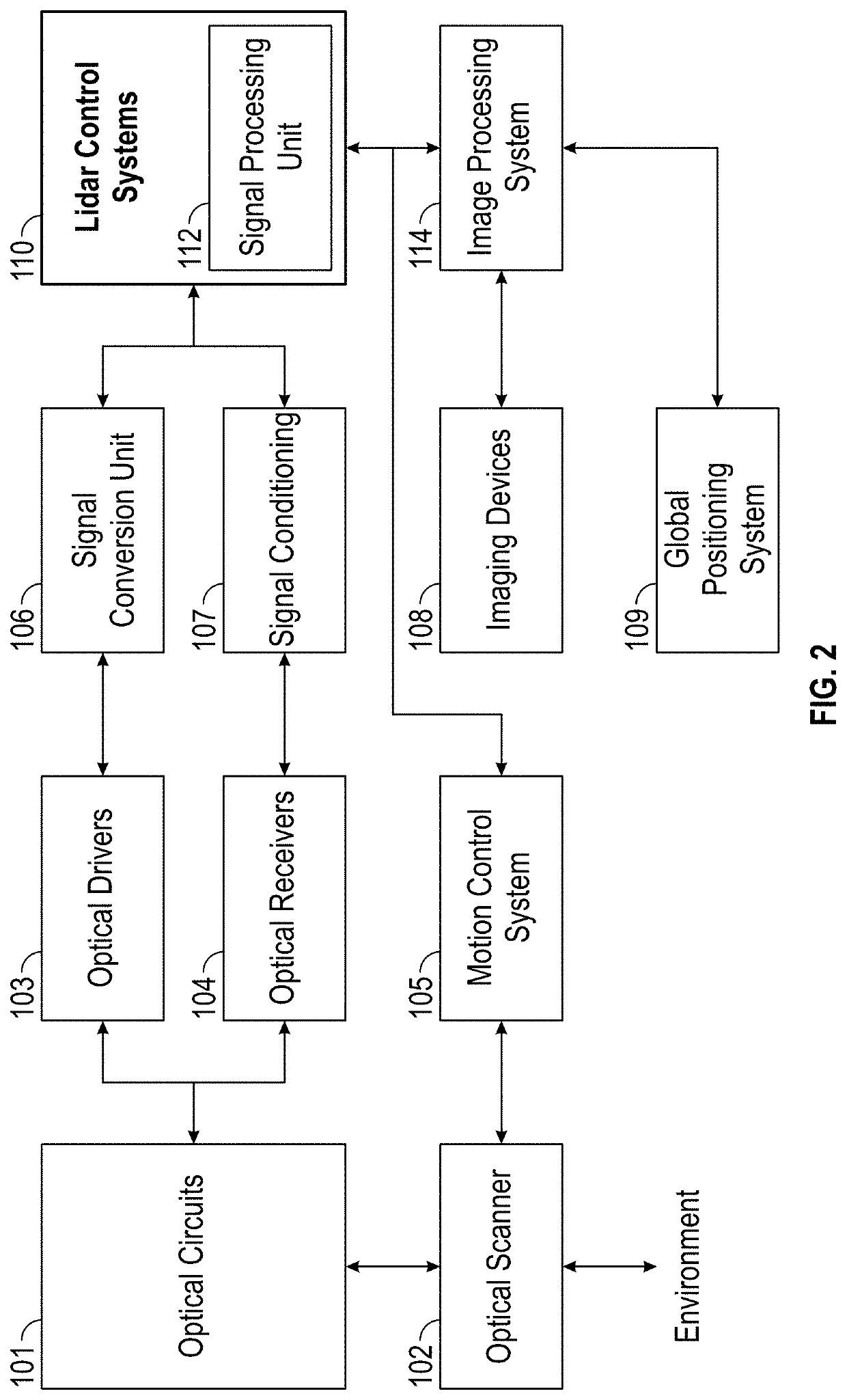
[0044]FIG. 2 illustrates ...


PUM


Abstract

A light detection and ranging (LIDAR) apparatus is provided that includes a laser source configured to emit a laser beam in a first direction. The apparatus also includes lensing optics configured to pass a first portion of the laser beam in the first direction toward a target, return a second portion of the laser beam into a return path as a local oscillator signal, and return a target signal into the return path. The apparatus also includes a quarter-wave plate configured to polarize the laser beam headed in the first direction and polarize the target signal returned through the lensing optics. The apparatus also includes a polarization beam splitter configured to pass non-polarized light through the beam splitter in the first direction and reflect polarized light in a second direction different than the first direction, wherein the polarization beam splitter is further configured to enable interference between the local oscillator signal and the target signal to generate a mixed signal. The apparatus also includes an optical detector configured to receive the mixed signal.

Description

TECHNOLOGICAL FIELD[0001]The present disclosure relates generally to light detection and ranging (LIDAR) that provides simultaneous measurement of range and velocity across two dimensions.BACKGROUND[0002]Fast-scanning mirrors are the primary components used to illuminate a scene in most conventional LIDAR systems. As shown in FIG. 1A, one mirror typically scans quickly along the X direction (azimuth), while another mirror scans slowly along the Y direction (elevation). Light emission and detection from target reflections are done coaxially, typically via a single mode fiber. The collected light has a measured delay or an altered frequency signature that is used to extract range, and potentially velocity, information. A 3D point cloud can be established when the point-wise detected range information is combined with angular position feedback from the scanning mirrors.[0003]To achieve higher frame rates, the mirror's angular velocity is increased, especially that of the scanner in fas...

Claims


Application Information

Patent Timeline
IPC IPC(8): G01S7/499G01S7/481G01S17/10
CPCG01S7/499G01S7/4812G01S7/4815G01S7/4817G01S17/10G01S7/4816G01S7/4811G01S17/58G01S7/4818
Inventor REZK, MINAOZA, NEAL N.GAGNE, KEITHKOCAOGLU, OMER P.
Owner AEVA INC
Why Eureka
Try Eureka