Method of producing micro-image elements on a substrate
a technology of micro-images and substrates, applied in the field of methods of producing micro-image elements on substrates, can solve the problems of limited resolution and size of micro-images that can be produced by printing methods that cannot be used to produce images requiring a resolution less than approximately 50 microns, limited roll-to-roll gravure printing of high-resolution features, etc., to achieve the effect of increasing the viscosity of lacquer
- Summary
- Abstract
- Description
- Claims
- Application Information
AI Technical Summary
Benefits of technology
Problems solved by technology
Method used
Image
Examples
example 2
[0131]The embossed relief layer of Example 1 was then overprinted with a silver ink (solvent based, solids content of 30% by volume, application via RK Coater meter bar no. 0). After the ink was dried, yielding a dry loading of 0.2 g / m2, the sheet of micro-lenses was again overlaid on the relief layer, as in Example 1.
[0132]When viewed through the micro-lenses in transmitted light, an integral image of a magnified “E”-symbol was clearly visible, with excellent contrast. The “E” symbol was approximately 1 cm×1 cm in size, and appeared to float approximately 1 cm above the plane of the micro-lenses. It was evident from the integral image that the ink had accumulated in a substantially uniform distribution on each of the microstructure units, flowing from the immediately surrounding regions of the “E”-shaped microstructure units (which were visibly ink-depleted in the integrated image compared to more distant regions in the base surface plane of the relief layer) into the recessed groo...
example 3
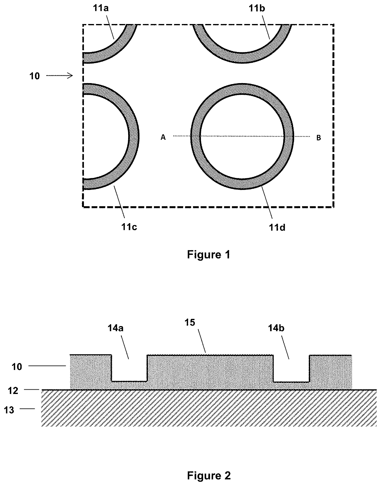
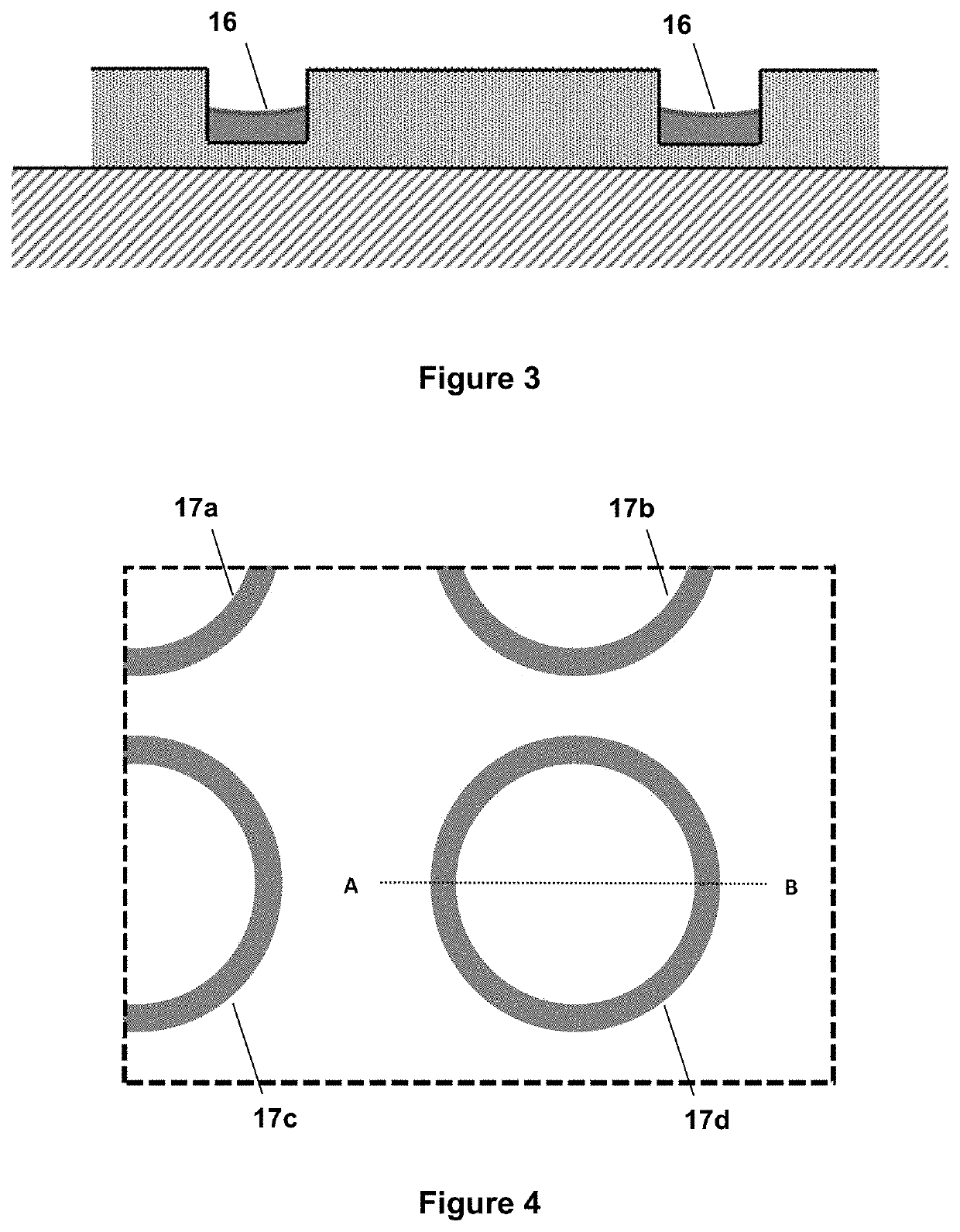
[0133]Another colourless, transparent relief layer comprising microstructure units was produced according to the method of Example 1. In this case, the embossed relief layer comprised an array of microstructure units in the form of “O”-shaped protruding ridges proud on the surface of the relief layer. The embossing height in the relief layer (i.e. the protrusion heights of the embossed features, corresponding to the depth of the recessed embossing elements on the shim) was approximately 1.8 microns. The width of the ridges forming the “O”-shapes was approximately 2 microns.
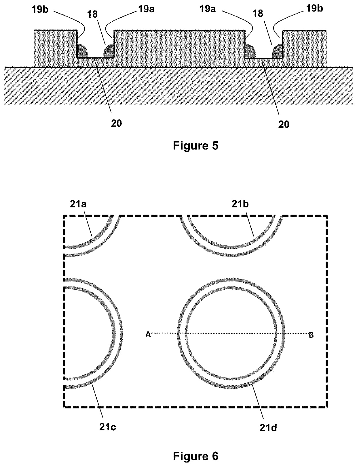
[0134]The embossed relief layer was then overprinted with a silver ink (solvent based, solids content of 30 by volume %, application via RK Coater meter bar no. 0. After the ink was dried in an oven, yielding a dry loading of 0.2 g / m2, the sheet of micro-lenses was again overlaid on the relief layer, as in Example 1.
[0135]When viewed through the micro-lenses in transmitted light, a magnified moiré image of a patte...
example 4
[0136]Another colourless, transparent relief layer comprising microstructure units was produced according to the method of Example 1. In this case, the microstructure units were hexagonally packed unit cells of a repeating hexagon pattern, extending over the surface of the relief layer. The fine lines of the hexagon pattern were recessed grooves embossed into surrounding regions of the relief layer. The hexagonal pattern had a pitch of approximately 53 microns. The embossing depth in the relief layer was approximately 1.7-1.8 microns. The minimum width of the grooves forming the pattern was approximately 1-2 microns.
[0137]The embossed relief layer was then overprinted with a black ink (solvent based, solids content of 20% by volume, viscosity of 19 seconds as measured with a Zahn cup #2; application via RK Coater meter bar no. 0) at a wet loading of 4 g / m2. After the ink was dry, the sheet of micro-lenses was again overlaid on the relief layer, as in Example 1.
[0138]When viewed thro...
PUM
| Property | Measurement | Unit |
|---|---|---|
| viscosity | aaaaa | aaaaa |
| viscosity | aaaaa | aaaaa |
| width | aaaaa | aaaaa |
Abstract
Description
Claims
Application Information
 - R&D
- Intellectual Property
- Life Sciences
- Materials
- Tech Scout
- Unparalleled Data Quality
- Higher Quality Content
- 60% Fewer Hallucinations
Browse by: Latest US Patents, China's latest patents, Technical Efficacy Thesaurus, Application Domain, Technology Topic, Popular Technical Reports.
© 2025 PatSnap. All rights reserved.Legal|Privacy policy|Modern Slavery Act Transparency Statement|Sitemap|About US| Contact US: help@patsnap.com


